Thyristor triggering pulse signal detecting circuit

A technology for triggering pulse and signal detection, which is applied in the direction of pulse characteristic measurement, measurement of electricity, and only voltage measurement, which can solve problems such as unreliable thyristor operation.

Active Publication Date: 2019-03-22
HNAC TECH
View PDF15 Cites 10 Cited by
  • Summary
  • Abstract
  • Description
  • Claims
  • Application Information

AI Technical Summary

Problems solved by technology

[0004] Based on this, it is necessary to provide a thyristor trigger pulse signal detection circuit for the problem th

Method used


Image

  • Thyristor triggering pulse signal detecting circuit
  • Thyristor triggering pulse signal detecting circuit
  • Thyristor triggering pulse signal detecting circuit

Examples


Embodiment Construction

[0020] In order to facilitate the understanding of the present application, the present application will be described more fully below with reference to the relevant drawings. Preferred embodiments of the application are shown in the accompanying drawings. However, the present application can be embodied in many different forms and is not limited to the embodiments described herein. On the contrary, the purpose of providing these embodiments is to make the understanding of the disclosure of the application more thorough and comprehensive.

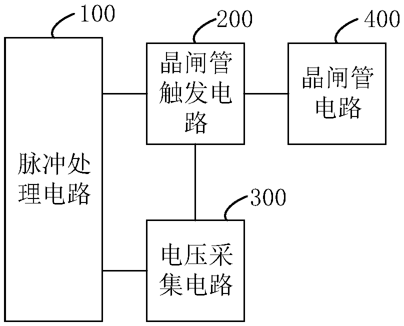
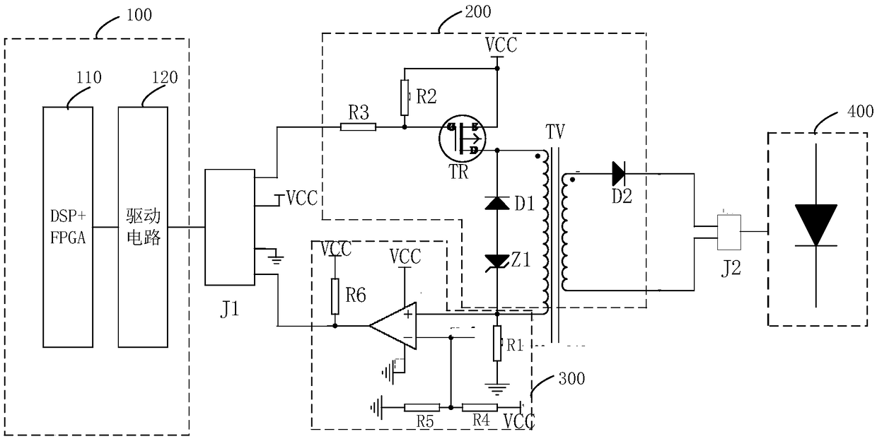
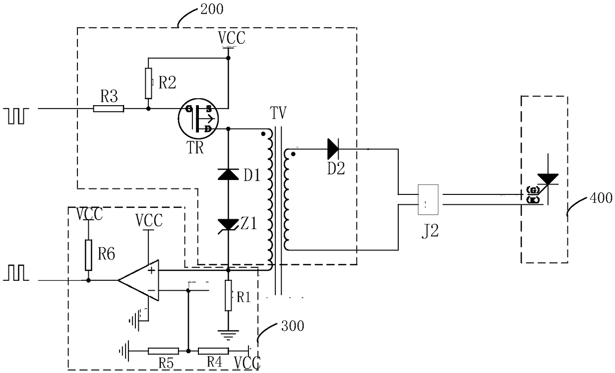
[0021] see figure 1 , a thyristor trigger pulse signal detection circuit, comprising: a pulse processing circuit 100 for outputting a pulse signal to a thyristor trigger circuit 200, and receiving and analyzing a voltage signal collected and sent by a voltage acquisition circuit 300 to obtain a detection result; the thyristor trigger circuit 200, used to drive the thyristor circuit 400 to work according to the pulse signal output by the p...


PUM


Abstract

The invention relates to a thyristor triggering pulse signal detecting circuit. A voltage at a primary winding side of a pulse transformer of a thyristor triggering circuit is collected through a voltage collecting circuit, and the collected voltage is sent to a pulse processing circuit for analyzing, a thyristor circuit connected with the thyristor triggering circuit in a current voltage is judged whether to operate normally, namely whether a short circuit or an open circuit occurs or not, so that a worker can make safety protection measures in time. Through the above thyristor triggering pulse signal detecting circuit, triggering pulse signal detection does not need to be directly performed in a thyristor, but through detecting a size of the voltage at the primary winding side of the pulse transformer of the thyristor triggering circuit, the thyristor circuit is indirectly judged whether to operate normally, namely whether a triggering pulse of the thyristor circuit is normal or not.Problems that triggering energy is consumed by direct measurement, and normal work of the thyristor circuit is affected are avoided from being generated.

Description

technical field [0001] The present application relates to the field of detection circuits, in particular to a thyristor trigger pulse signal detection circuit. Background technique [0002] Thyristor (Thyristor) is a thyristor, also known as a silicon controlled rectifier. Since a thyristor can work under high voltage and high current conditions, and its working process can be controlled, it is widely used in controllable rectification, AC In electronic circuits such as voltage regulators, non-contact electronic switches, inverters and frequency converters. In a large-scale excitation system, in order to ensure the power generation safety of the entire system, it is often necessary to set up a corresponding circuit to detect the pulse signal of the thyristor rectifier bridge of the excitation system, so as to take safety protection measures when the pulse is lost or abnormal. [0003] The traditional thyristor trigger pulse signal detection method is to collect the voltage ...

Claims


Application Information

Patent Timeline
IPC IPC(8): G01R29/02G01R19/00G01R31/02
CPCG01R19/0084G01R29/02G01R31/50
Inventor 廖晓斌桂勇华胡清波刘伟
Owner HNAC TECH
Why Eureka
Try Eureka