
Ultra-high-speed single-photon imaging device for photon camera

An imaging device, ultra-high-speed technology, applied to cameras, measuring devices, camera bodies, etc., can solve problems such as excessive heat, device damage, and affecting normal operation of the device, and achieve increased heat dissipation area, good protection, and good buffering The effect of shock absorption

Inactive Publication Date: 2019-09-27
TS INVESTMENT CASTING
View PDF0 Cites 0 Cited by
  • Summary
  • Abstract
  • Description
  • Claims
  • Application Information

AI Technical Summary

Problems solved by technology

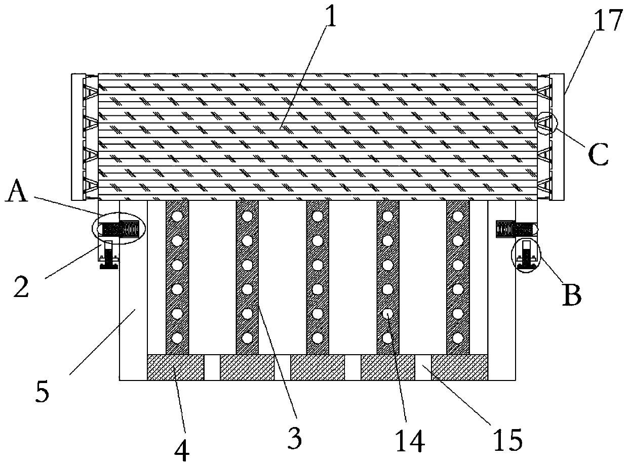
[0004] The purpose of the present invention is to solve the problem that the single-photon imaging device in the prior art will generate more heat due to efficient use, and if the heat cannot be dissipated in time, it will affect the normal operation of the device and even cause damage to the device , and proposed a photon camera ultra-high-speed single-photon imaging device

Method used


Image

  • Ultra-high-speed single-photon imaging device for photon camera
  • Ultra-high-speed single-photon imaging device for photon camera
  • Ultra-high-speed single-photon imaging device for photon camera

Examples


Embodiment Construction

[0023] The technical solutions in the embodiments of the present invention will be clearly and completely described below with reference to the accompanying drawings in the embodiments of the present invention. Obviously, the described embodiments are only a part of the embodiments of the present invention, but not all of the embodiments.

[0024] In the description of the present invention, it should be understood that the terms "upper", "lower", "front", "rear", "left", "right", "top", "bottom", "inside", " The orientation or positional relationship indicated by "outside" is based on the orientation or positional relationship shown in the accompanying drawings, and is only for the convenience of describing the present invention and simplifying the description, rather than indicating or implying that the indicated device or element must have a specific orientation, so as to The specific orientation configuration and operation are therefore not to be construed as limitations of...


PUM


Abstract

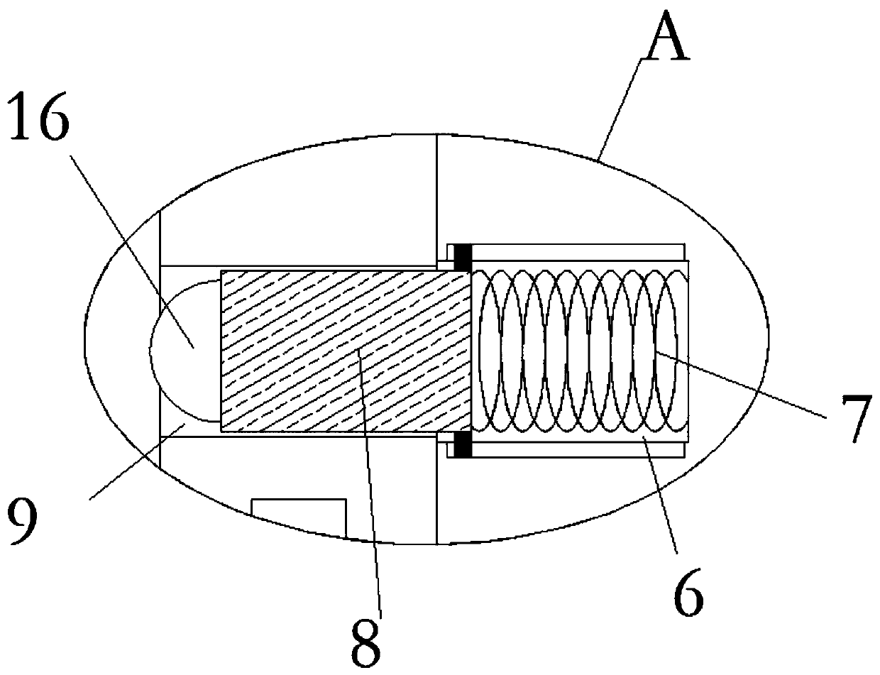
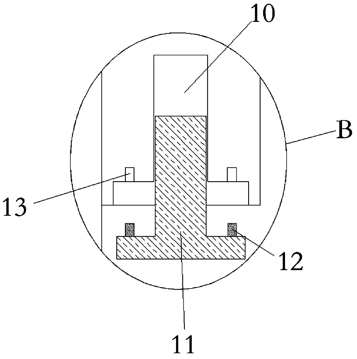
The invention discloses an ultra-high-speed single-photon imaging device for a photon camera. The ultra-high-speed single-photon imaging device comprises an imaging device body; two fixing plates are symmetrically and fixedly connected to the left side and right side of the lower end of the imaging device body; the lower end of the imaging device body is in contact connection with a plurality of heat dissipation rods; the lower ends of the plurality of heat dissipation rods are fixedly connected with the same heat dissipation plate; the left end and right end of the heat dissipation plate are fixedly connected with clamping plates; cylindrical grooves are formed in one side of one of the clamping plates and one side of the other clamping plate which are far away from each other; reset springs are arranged in the cylindrical grooves; one end of each reset spring is fixedly connected with the inner wall of the corresponding cylindrical groove, and the other ends of the reset springs are fixedly connected with limiting rods respectively; limiting holes matched with the limiting rods are formed in the surface of the fixing plates; T-shaped grooves are formed in the lower ends of the fixing plates; and T-shaped rods are clamped into the T-shaped grooves. The device disclosed by the invention has the advantages of simple and reasonable structural design and convenience in operation. With the ultra-high-speed single-photon imaging device for the photon camera adopted, the problem of the influence of heat accumulation on the normal operation of the imaging device body can be avoided.

Description

technical field [0001] The invention relates to the technical field of photonic cameras, in particular to an ultra-high-speed single-photon imaging device for photonic cameras. Background technique [0002] In the fields of particle tracking, quantum radar, star detection, radiation imaging, etc., when the detected optical signal reaches the single-photon level, that is, when the discrete single-photon incident state is displayed, its imaging will become very difficult. Single-photon detection technology is used in high-resolution spectral measurement, non-destructive material analysis, high-speed phenomenon detection, precision analysis, atmospheric pollution measurement, bioluminescence, radiation detection, high-energy physics, astronomical photometry, optical time-domain emission, quantum encryption Distribution systems and other fields have a wide range of applications. Due to the important position of single photon detector in the high-tech field, it has become one of...

Claims


Application Information

Patent Timeline
Patent Type & Authority Applications(China)
IPC IPC(8): G01J1/44G01J1/04G03B17/55G03B17/56
CPCG01J1/44G01J1/0403G03B17/55G03B17/561G01J2001/442
Inventor 王震球
Owner TS INVESTMENT CASTING
Learn More