Filter syringe and method

A technology for a syringe and a filter membrane, applied in the field of syringe filter devices, can solve the problems of troublesome repetitive operations, difficult automation, and easily blocked filters.

Inactive Publication Date: 2019-03-26
杨用武
View PDF8 Cites 0 Cited by
  • Summary
  • Abstract
  • Description
  • Claims
  • Application Information

AI Technical Summary

Problems solved by technology

This syringe application is difficult to automate
First, the filter gets clogged easily
Second, the process of repeating operations is cumbersome and limited to low pressure applications
[0012] The present invention provides a syringe device, system and method to make the filtration process more efficient and address the limitations of existing filtration devices

Method used


Image

  • Filter syringe and method
  • Filter syringe and method
  • Filter syringe and method

Examples


Embodiment Construction

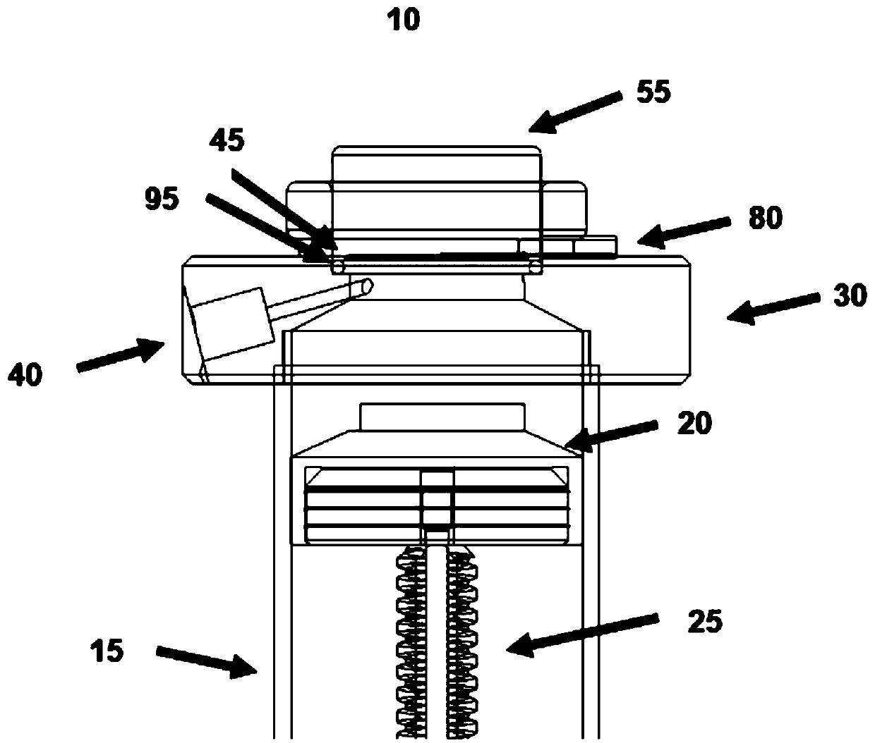
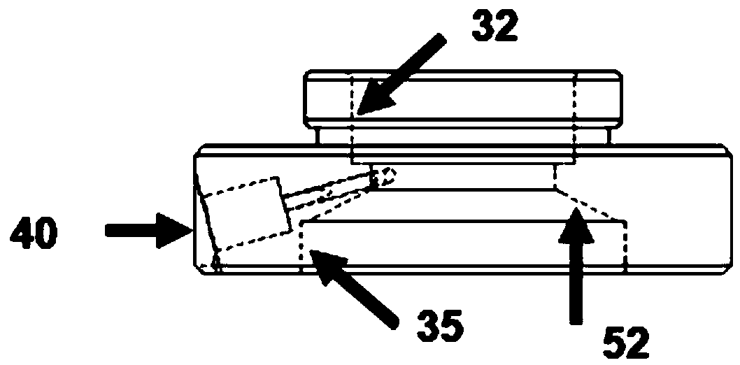
[0063] In a variant, see generally Figure 1 to Figure 15 , the syringe 10 has a cylindrical barrel 15, and a piston 20 connected to the piston rod 25, the piston 20 is fitted to be adapted to slide axially within the cylindrical barrel 15. The end cap 30 has a circular hole 35 at the bottom, which fits tightly on the cylinder 15 in an airtight and liquidtight manner. Top circular hole 32 is used to receive O-ring 95 , filter membrane 45 and stop cap 55 . The round hole 35 has a conical cone 52 .

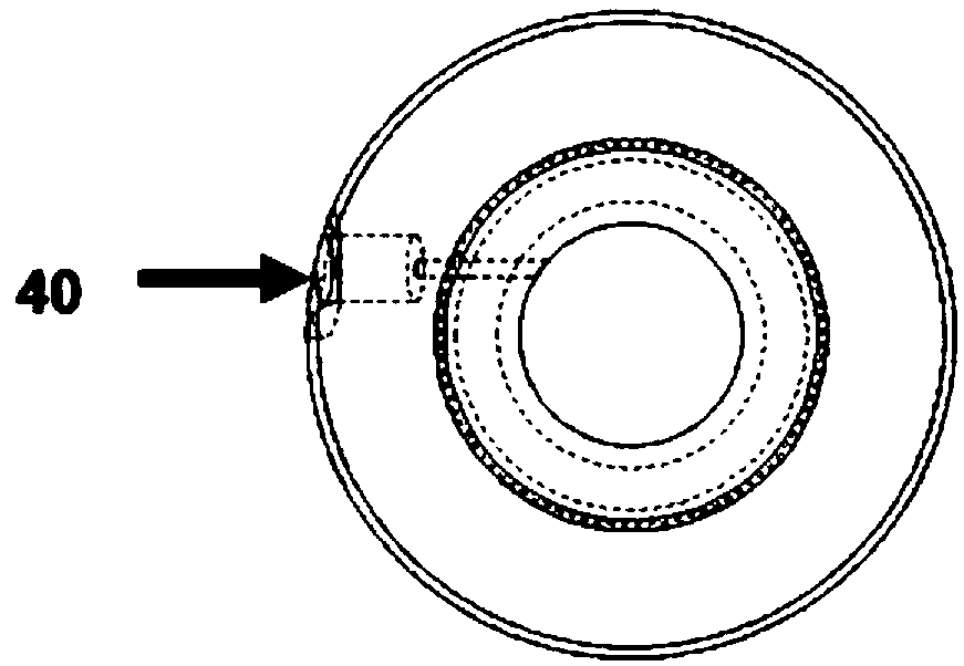
[0064] In another variant, such as Figure 2a As shown in -2b, the end cap 30 has an off-center inlet 40 on the side below the filter membrane surface 45 . The inlet 40 is sloped at an angle towards the filter membrane surface 45 . When the piston 20 slides down, due to the inclined position of the inlet 40, the liquid sample or solvent is sucked in from the inlet 40 and splashes the filter membrane 45, and because of its eccentric design, the liquid from the inlet 40 is generat...


PUM


Abstract

The invention provides a syringe filtering system and method. The syringe filtering system comprises a cylindrical cylinder, a piston, a piston rod and at least one outlet, an end cover with at leastone inlet, and a motor controlled by the microcontroller, a filter membrane, a round hole and a stop cover. The piston is configured to slide up and down in the cylindrical cylinder. The liquid is received, mixed, filtered and collected by an inlet in the end cover.

Description

[0001] Cross References to Related Applications [0002] This application claims priority to U.S. Provisional Application Serial No. 62 / 614,292, filed January 5, 2018, the entire contents of which are hereby incorporated by reference. technical field [0003] The present invention relates to syringe filtration devices and methods. Background technique [0004] The filtration process of biological samples and colloids has a wide range of applications in research laboratories, biotechnology, pharmaceutical and food industries. Some examples of such applications are disclosed in previous patents: US4018752A, US4341801A, US4680122A, US4897465A, US5342863A, US6417251B1 and US6582385B2. In filtration, solutes and co-solvents in a sample solution are separated by their size through a semipermeable membrane. According to the pore size of the membrane, the filtration process is divided into microfiltration (~0.1-10 micrometers), ultrafiltration (~1-100 nanometers) and nanofiltratio...

Claims


Application Information

Patent Timeline
Patent Type & Authority Applications(China)
IPC IPC(8): B01D61/00B01D65/00B01F13/00G01N1/40G01N1/34
CPCB01D61/00B01D65/00G01N1/34G01N1/40B01F33/50112
Inventor 杨用武张弛
Owner 杨用武
Why Eureka
Try Eureka