
Flour machine with drying function

A drying function, flour mill technology, applied in grain processing and other directions, can solve the problems of flour without good preservation equipment, poor quality, and difficult to preserve, and achieve the effect of ensuring quality problems, improving quality, and increasing feeding speed.

Inactive Publication Date: 2019-03-26
周力
View PDF18 Cites 0 Cited by
  • Summary
  • Abstract
  • Description
  • Claims
  • Application Information

AI Technical Summary

Problems solved by technology

However, this device does not dry the materials, and the flour from wet materials is not easy to store, and the quality is not good; there is no good storage equipment for the ground flour

Method used


Image

  • Flour machine with drying function
  • Flour machine with drying function
  • Flour machine with drying function

Examples


Embodiment 1

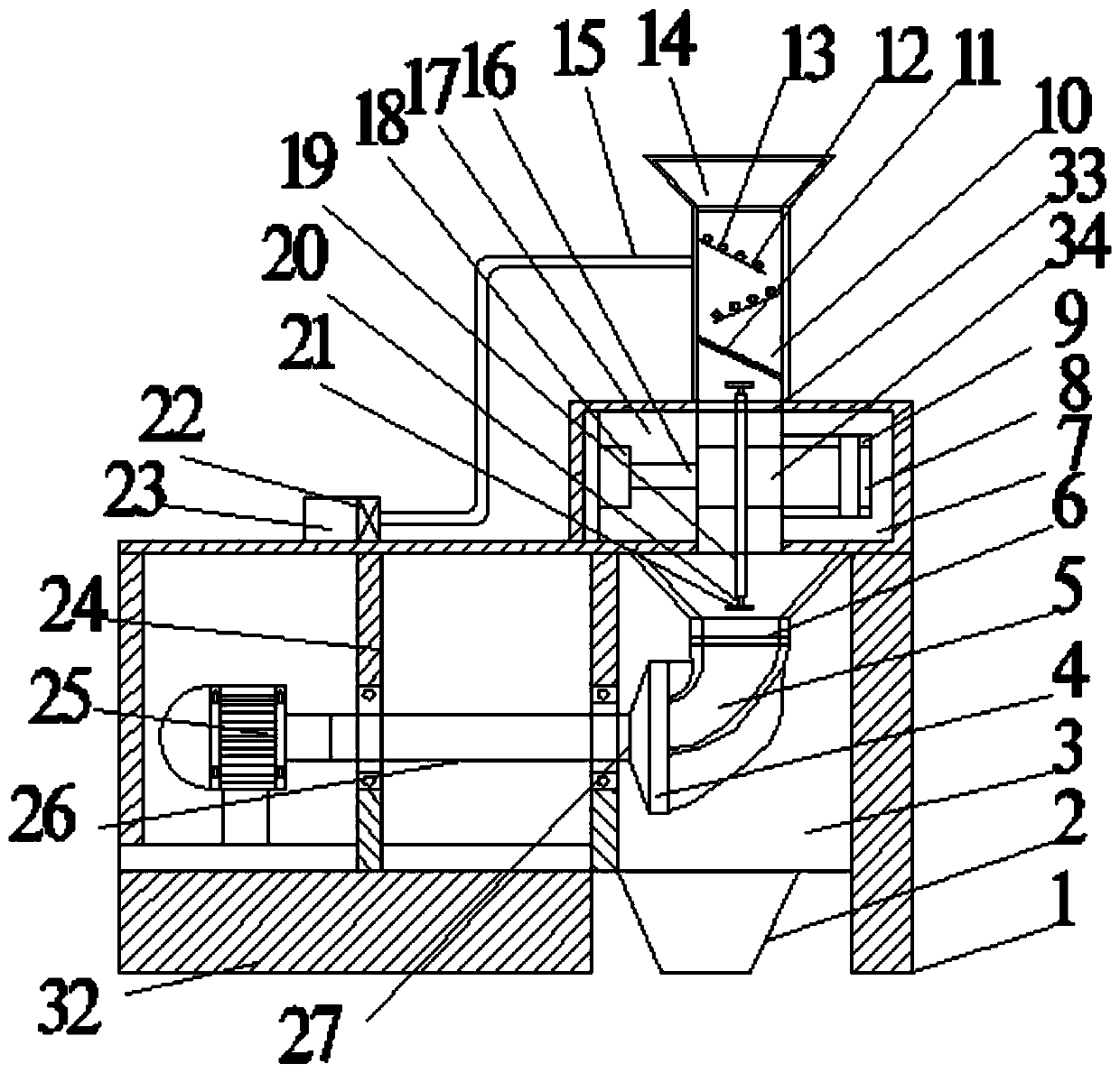
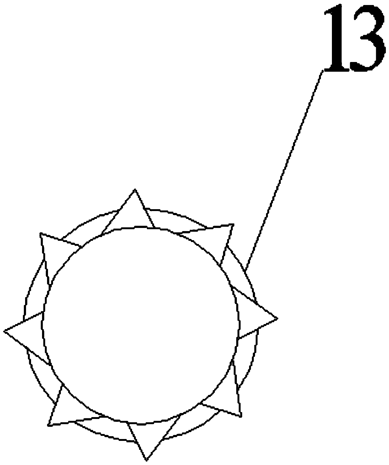
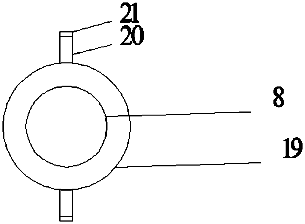
[0024] see Figure 1-3 , a flour machine with a drying function, comprising a base 32 and a flour milling chamber 3, the top of the base 32 is provided with a first motor 25, the output shaft of the first motor 25 passes through the supporting column 24 and is connected to one end of the rotating shaft 26 for rotation , the other end of the rotating shaft 26 is fixedly connected with a shaft coupling 27, and the shaft coupling 27 is fixedly connected with the noodle grinder 4. By starting the first motor 25, the operation of the noodle grinder 4 is driven. The flour mill 4 is arranged on one side of the flour milling chamber 3 , and the other side of the flour milling chamber 3 is provided with a support 1 . One side of the noodle grinder 4 is connected with a noodle delivery pipeline 5, and the top of the noodle delivery pipeline 5 is connected with a one-way valve 6, and the one-way valve 6 prevents the backflow of flour. A noodle storage tank 2 is arranged below the noodl...

Embodiment 2

[0028] refer to Figure 4 , on the basis of Embodiment 1, the bottom of the surface storage tank 2 is provided with a heating base 28, and the inside of the heating base 28 is provided with a pipe row 29, and one side of the heating base 28 is communicated with an air supply pipeline 30, and the air supply pipeline 30 is connected to To the air outlet pipe of heating fan 31. By sending the hot air in the heating fan 31 into the row pipe 29, then the bottom of the noodle storage tank 2 is heated by the row pipe 29, thereby preventing the bottom of the noodle storage tank 2 from damaging the quality of the flour due to moisture.


PUM


Abstract

The invention relates to the technical field of grain processing technologies and discloses a flour machine with a drying function. The flour machine comprises a base and a flour milling chamber. A first motor is arranged at the upper portion of the base, and an output shaft of the first motor penetrates a supporting pillar and is rotationally connected with one end of a rotating shaft. The otherend of the rotating shaft is fixedly connected with a coupler. The coupler is fixedly connected to a flour mill. The flour mill is arranged on one side of the flour milling chamber, and one side of the flour mill communicates with a flour conveying pipeline. The top of the flour milling chamber communicates with a feeding pipe, and a fixing block is welded to the top of the flour milling chamber.A feeding opening is welded to the top of the fixing block, and a drying chamber is arranged above the feeding opening. Multiple material guide plates are obliquely arranged in the drying chamber, androtating rollers are arranged above the material guide plates. One side wall of the drying chamber communicates with a gas conveying pipe, the bottom end of the gas conveying pipe communicates with aheater, and one side of the heater communicates with an air blower. The flour machine has the beneficial effects that materials can be dried, and a good storage environment can be provided for the materials and milled flour.

Description

technical field [0001] The invention relates to the technical field of grain technology processing, in particular to a flour mill with a drying function. Background technique [0002] Grain refers to grains, including three major categories of crops: wheat, coarse grains and rice. In the process of food production and processing into food [0003] In the process, the most common step is to grind the grain, but the existing grain grinder often cannot control the grinding process. [0004] The feeding speed in the process, when the feeding speed is too fast, the grain cannot be fully ground, causing the equipment to carry a heavy burden, and may even damage the machine; while the feeding speed is too slow, the efficiency will be low, which is very troublesome. [0005] Chinese patent (notification number: CN 2207138011 U, announcement date: 2018.03.27) The invention discloses a flour mill with controllable feeding, including a protective shell, and a support plate is fixedly...

Claims


Application Information

Patent Timeline
Patent Type & Authority Applications(China)
IPC IPC(8): B02C9/04B02C11/04
CPCB02C9/04B02C11/04
Inventor 周力李娜
Owner 周力
Learn More