Glue spraying clamp

A fixture and glue spraying technology, which is applied in the direction of spraying devices, coatings, and liquid coating devices on the surface, can solve the problems of moving pieces, unstable fixing of pieces, and inability to use common pieces, etc., and achieves strong applicability , the effect of preventing sagging deformation

Pending Publication Date: 2019-03-26
南方佛吉亚汽车部件有限公司
View PDF9 Cites 1 Cited by
  • Summary
  • Abstract
  • Description
  • Claims
  • Application Information

AI Technical Summary

Problems solved by technology

[0002] At present, the glue spraying fixture generally adopts profiling tooling, and the pieces are not fixed stably. When spraying glue, the airflow of the spray gun can easily move the pieces. High-quality cutting pieces, but in the process of spraying glue on the back, the high-speed atomized glue is very easy to pollute the surface of the cutting pieces, and the tooling is special tooling, and the cutting pieces of different structures cannot be used universally.

Method used


Image

  • Glue spraying clamp

Examples


Embodiment Construction

[0013] The present invention is further described in conjunction with the following examples.

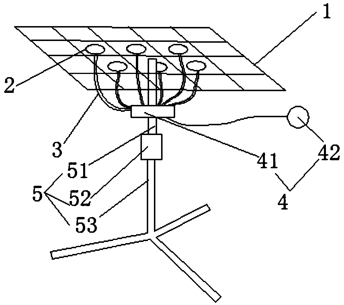
[0014] A specific embodiment of a glue spraying fixture of the present invention, such as figure 1 As shown, it includes a hollow bracket 1 , a rotating bracket 5 , a vacuum device 4 and a plurality of suction cups 2 . As a preferred solution, the rotating bracket 5 includes a fixed bracket 53 and a rotating rod 51. The middle part of the fixing bracket 53 extends upwards to a fixed post, and the bottom end of the rotating rod 51 is connected to the fixed post through a sleeve 52. Of course, except The sleeve 52 is selected, and the bearing can also be used as a rotating part for connection. The rotating end of the rotating bracket 5 (the top end of the rotating rod 51) is fixedly connected with the hollow bracket 1, and the vacuum device 4 is fixedly installed on the rotating bracket 5. Specifically, the vacuum device 4 can be fixedly installed on the rotating rod 51 or fixedly in...


PUM


Abstract

The invention relates to the technical field of clamps, in particular to a glue spraying clamp. The glue spraying clamp comprises a hollow-out bracket, a rotary bracket, a vacuum device and a plurality of sucking discs, wherein the rotary end of the rotary bracket is fixedly connected with the hollow-out bracket; the vacuum device is fixedly mounted on the rotary bracket; each sucking disc communicates with the vacuum device through a pipeline, and is distributed on a hollow-out part of the hollow-out bracket; and under a working state, the vacuum device extracts air, so that negative pressureis formed at the working ends of the sucking discs for adsorbing products on the hollow-out bracket. Compared with the prior art, the rotary bracket can be controlled, so that a glue-sprayed productis driven to rotate for performing glue spraying to different areas of a product; and the positions and the angles of the sucking discs can be regulated through the movable pipeline for adsorbing products of different shapes, so that the glue spraying clamp has relatively strong applicable performance.

Description

technical field [0001] The invention relates to the technical field of fixtures, in particular to a glue spraying fixture. Background technique [0002] At present, the glue spraying fixture generally adopts profiling tooling, and the pieces are not fixed stably. When spraying glue, the airflow of the spray gun can easily move the pieces. High-quality cut pieces, but in the process of spraying glue on the back, the high-speed atomized glue can easily pollute the surface of the cut pieces, and the tooling is all special tooling, and the pieces with different structures cannot be used universally. Contents of the invention [0003] The object of the present invention is to provide a glue spraying fixture with simple structure and strong applicability in order to solve the deficiencies in the prior art. [0004] The purpose of the present invention is achieved through the following technical solutions: provide a glue spraying fixture, including a hollow bracket, a rotating b...

Claims


Application Information

Patent Timeline
Patent Type & Authority Applications(China)
IPC IPC(8): B05C13/02B05B13/02
CPCB05B13/0228B05C13/02
Inventor 杨毕学顾威浩
Owner 南方佛吉亚汽车部件有限公司
Why Eureka
Try Eureka