
Instrument placement device capable of freely switching box frame for bridge construction

A technology for bridge construction and box racking, which is used in tool storage devices, manufacturing tools, etc., can solve the problems of inconvenient access, difficulty in finding, and harsh working environment.

Inactive Publication Date: 2019-03-26
颜全聪
View PDF0 Cites 4 Cited by
  • Summary
  • Abstract
  • Description
  • Claims
  • Application Information

AI Technical Summary

Problems solved by technology

[0002] A large number of equipment and instruments are often needed in bridge construction, and due to the harsh working environment, the instrument is usually placed in the instrument placement device to ensure that it will not be damaged. During construction, since the instrument placement device adopts a fixed structure, during bridge construction There are a lot of instruments used, and in order to avoid the convenience of finding the instruments, they need to be stored in different categories. Therefore, the designed instrument placement device is relatively large. Due to the fact that in some low-level construction environments, it is inevitable that it will be relatively inconvenient to pick and place. ; and in order to improve work efficiency, users need to carry the instruments they use with them. Therefore, the instruments are often thrown away randomly due to the user's carelessness, causing the problem of finding it difficult.

Method used


Image

  • Instrument placement device capable of freely switching box frame for bridge construction
  • Instrument placement device capable of freely switching box frame for bridge construction
  • Instrument placement device capable of freely switching box frame for bridge construction

Examples


Embodiment

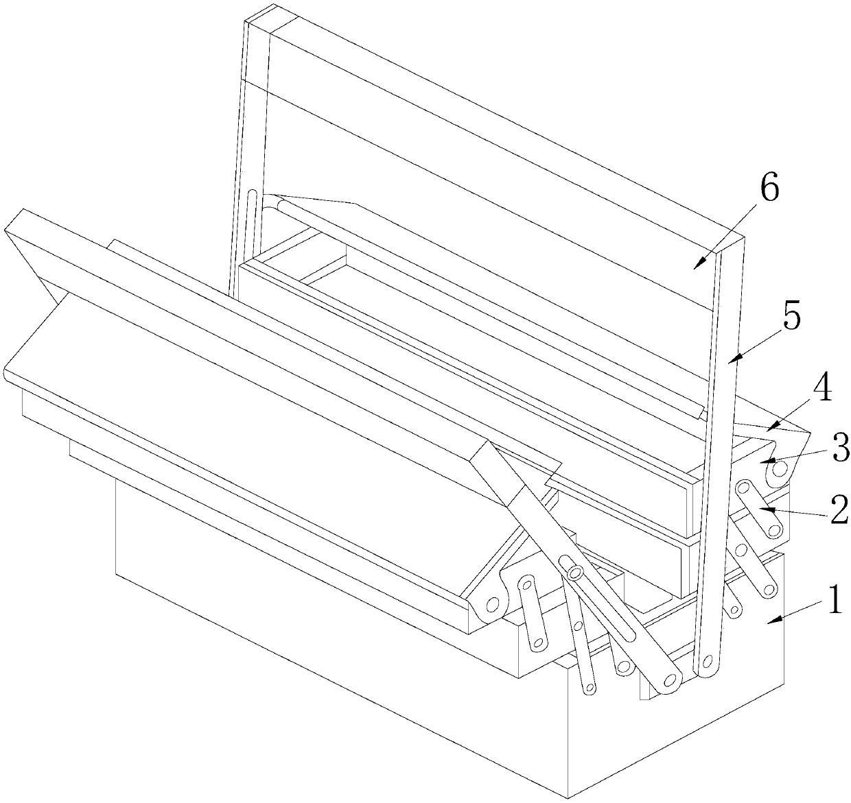
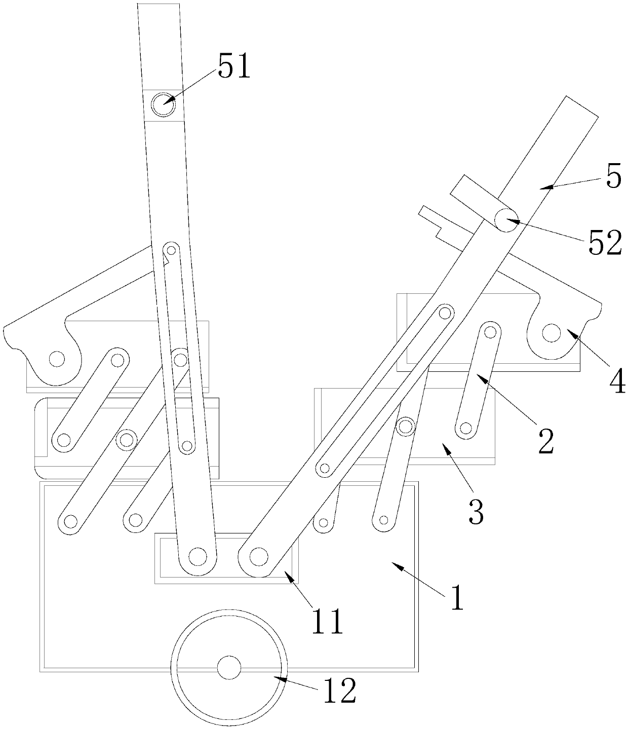
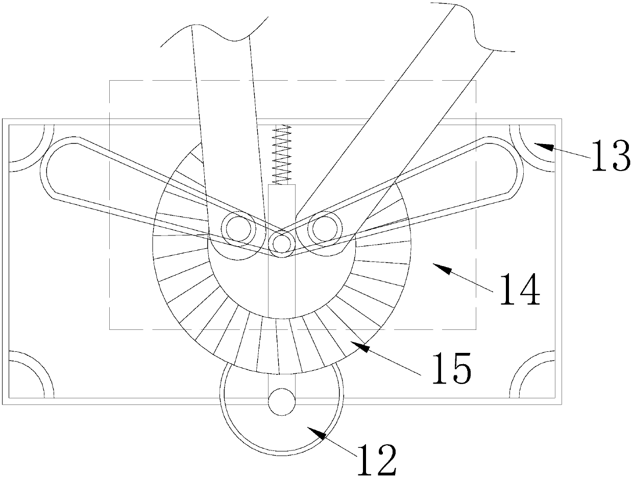
[0028] Such as Figure 1-Figure 5 As shown, the present invention provides an instrument placement device for bridge construction to realize free switching of box frames.

[0029] The working principle of the instrument placement device in the above-mentioned technical scheme is described as follows: its structure includes a bottom box 1, a swing bar 2, a storage box 3, a movable case cover 4, a movable handle 5, and a closing plate 6. The sides of the bottom box 1 are respectively provided with two movable handles 5 which are movably matched with each other through the deck 11, and the two matched movable handles 5 are respectively provided with a latch 51 and a buckle 52 which are engaged with each other. Both sides of the bottom of the bottom box 1 are mechanically connected with walking wheels 12 of equal structure through bearings, and the storage box 3 is provided with more than two and evenly distributed on both sides of the bottom box 1, and between two The swing rod ...


PUM


Abstract

The invention discloses an instrument placement device capable of freely switching a box frame for bridge construction. The instrument placement device capable of freely switching the box frame for bridge construction structurally comprises a bottom box, an oscillating bar, a storage box, a movable box cover, movable lifting handles, and an opening-closing plate, wherein the two movable lifting handles movably matched with each other through a clamping seat are arranged on the sides of the bottom box; clamping bolts and clamping buckles fastened with each other are arranged on the two matchedmovable lifting handles; the movable lifting handles are matched with extension springs; the clamping bolts and the clamping buckles are arranged on the movable lifting handles and are fastened, so that a handheld type instrument placement device is realized; the clamping bolts and the clamping buckles are opened, the movable lifting hands rotate in the opposite direction under the matching of theextension springs and the opening-closing plate, and a cover plate is opened and fixed onto the ground, so that a perpendicular frame type instrument placement device is realized; and two modes of the box frame are switched conveniently, the fixed type is changed to be the movable type, instruments are taken and placed conveniently, and the instrument placement device can move any time any whereat multiple angles with the opening-closing angles being 45 degrees, 60 degrees and 90 degrees without influencing operation, can be carried conveniently, and is suitable for multiple working environments.

Description

technical field [0001] The invention relates to an instrument placement device, in particular to an instrument placement device for bridge construction to realize free switching of box frames. Background technique [0002] A large number of equipment and instruments are often needed in bridge construction, and due to the harsh working environment, the instrument is usually placed in the instrument placement device to ensure that it will not be damaged. During construction, since the instrument placement device adopts a fixed structure, during bridge construction There are a lot of instruments used, and in order to avoid the convenience of finding the instruments, they need to be stored in different categories. Therefore, the designed instrument placement device is relatively large. Due to the fact that in some low-level construction environments, it is inevitable that it will be relatively inconvenient to pick and place. ; And in order to improve work efficiency, the user ju...

Claims


Application Information

Patent Timeline
Patent Type & Authority Applications(China)
IPC IPC(8): B25H3/02
CPCB25H3/02
Inventor 颜全聪
Owner 颜全聪
Learn More