Plug-in adjustable exhaust pipe connecting structure and assembly method
A connection structure and adjustable technology, which is applied in the direction of exhaust devices, mufflers, engine components, etc., can solve problems such as easy wear, unguaranteed coaxiality, inconsistent installation status, etc., so as to improve service life and ensure The effect of assembly accuracy and airtightness assurance
- Summary
- Abstract
- Description
- Claims
- Application Information
AI Technical Summary
Problems solved by technology
Method used
Image

Examples
Embodiment 1
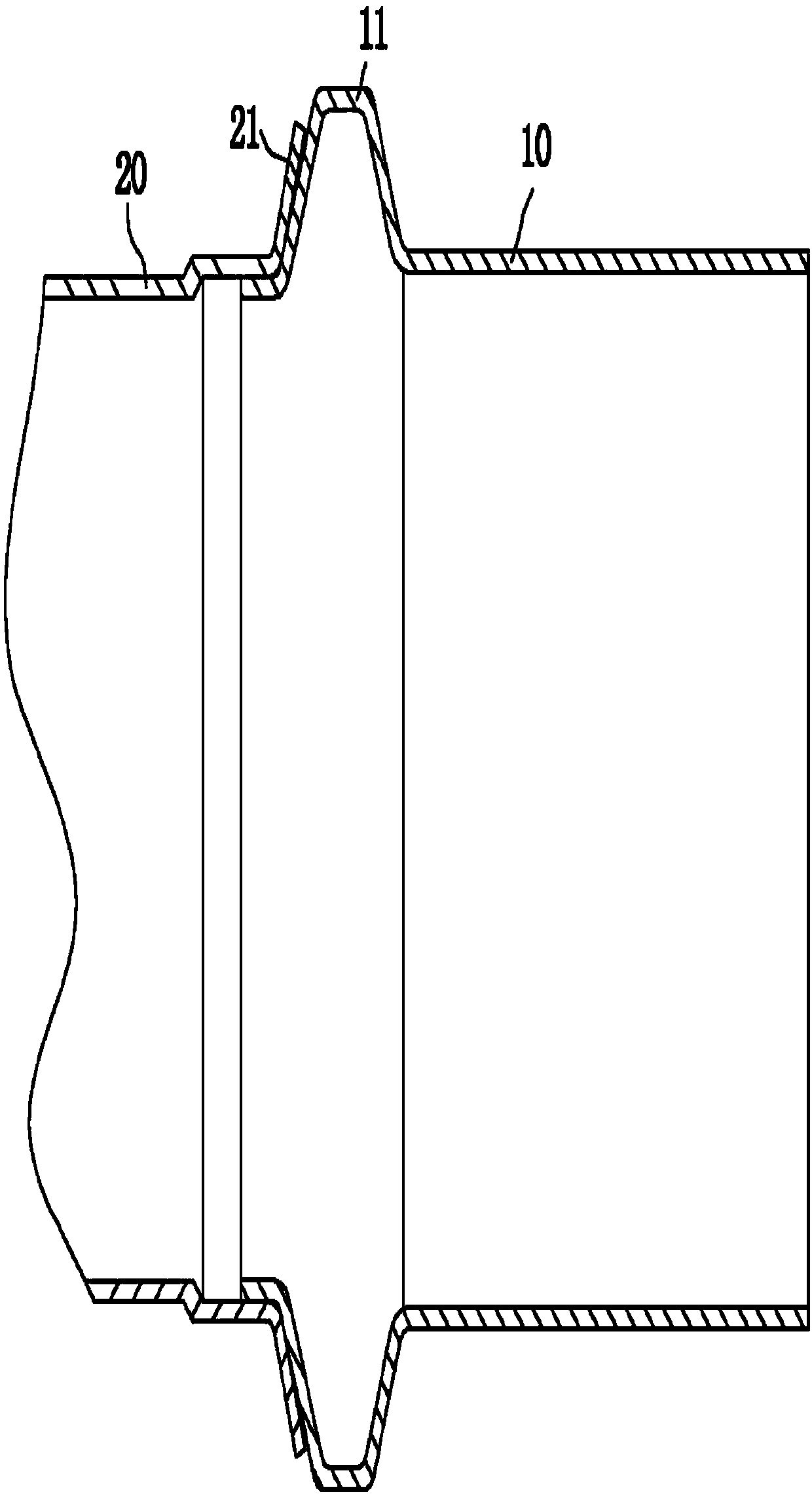
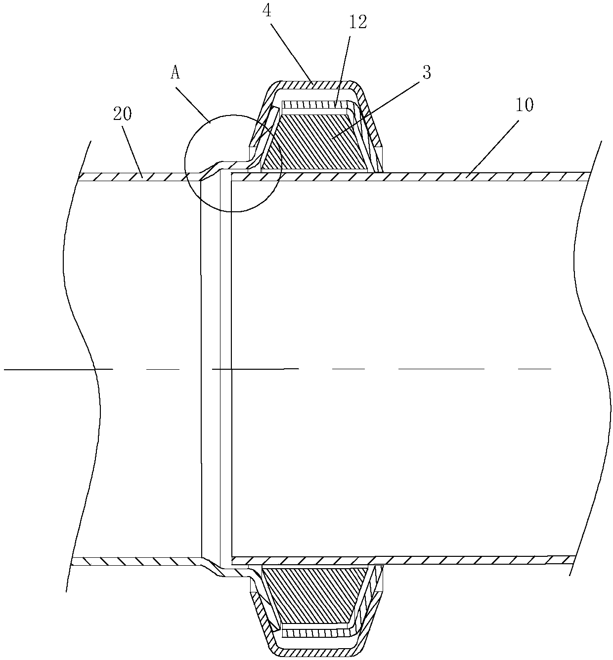
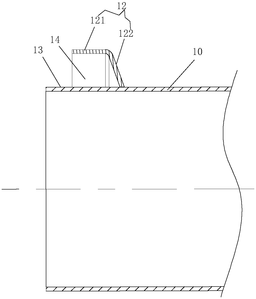
[0020] Example 1 as Figure 2 to Figure 6 As shown, the plug-in adjustable exhaust pipe connection structure of this embodiment includes: the first pipe 10, the second pipe 20, the annular asbestos pad 3 and the clamp 4, and the two joints of the clamp 4 are provided with connecting ears 41 The connecting ear 41 is provided with a screw hole suitable for the passage of the stop pin 42, and the outer wall of the connecting part of the first pipe 10 is provided with an integrally formed 7-shaped protrusion 12 along the circumference, and the 7-shaped protrusion 12 includes an inclined side wall 122 and Annular side wall 121, the annular side wall 121 is arranged coaxially with the first pipe 10, the inner side end of the annular side wall 121 is fixedly connected with the outer wall of the first pipe 10 through the inclined side wall 122, and the front end of the first pipe 10 protrudes from the ring The outer end of the side wall 121 is arranged to form a socket 13, and the len...
Embodiment 2
[0022] The assembly method of the plug-in adjustable exhaust pipe connection structure described in Embodiment 1 includes the following steps:
[0023] A. Set the ring-shaped asbestos pad 3 with trapezoidal cross-section in the cavity 14 of the 7-shaped protrusion 12 at the front end of the first pipe 10 .
[0024] B. Insert the insertion part 13 at the front end of the first pipeline 10 into the second pipeline 20, the insertion part 10 is placed in the tight side 22 and the front end of the insertion part 13 is blocked and limited by the transition side 23 to avoid over-insertion more; at this time, the top of the trumpet-shaped flange 21 of the second pipeline 20 is in contact with the outer end of the 7-shaped raised annular side wall 121, so as to close the cavity 14 and limit the asbestos pad 3 in the cavity 14 At the same time, the outer flange 21 squeezes the inclined side wall 122 of the asbestos pad 3 to form a seal and reduce leakage at the joint.
[0025] C. Put t...
PUM
 Abstract
Description
Claims
Application Information
 - R&D
- Intellectual Property
- Life Sciences
- Materials
- Tech Scout
- Unparalleled Data Quality
- Higher Quality Content
- 60% Fewer Hallucinations
Browse by: Latest US Patents, China's latest patents, Technical Efficacy Thesaurus, Application Domain, Technology Topic, Popular Technical Reports.
© 2025 PatSnap. All rights reserved.Legal|Privacy policy|Modern Slavery Act Transparency Statement|Sitemap|About US| Contact US: help@patsnap.com