LED light emitting device

A light-emitting device, LED light source technology, applied in the direction of lighting devices, fixed lighting devices, lighting device light guides, etc., can solve the problems of difficult design of light guide plate outlets, large number of LEDs, etc., to eliminate Hotspot defects and reduce cost, and the effect of reducing design difficulty

Inactive Publication Date: 2019-03-26
TPV ELECTRONICS (FUJIAN) CO LTD
View PDF5 Cites 0 Cited by
  • Summary
  • Abstract
  • Description
  • Claims
  • Application Information

AI Technical Summary

Problems solved by technology

Since the light of the LED enters the light guide plate at a certain angle, there is an angle blind area (that is, a shadow area) between the two LEDs, which will cause obvious firefly (hotspot) in the display area of ​​the liquid crystal display device or LED lighting equipment. ) bad phenomenon; in the prior art, in order to solve this hotspot bad phenomenon, it is usually reinforced by increasing the number of LEDs and increasing the dot design of the light guide plate.

Method used


Image

  • LED light emitting device
  • LED light emitting device

Examples


Embodiment Construction

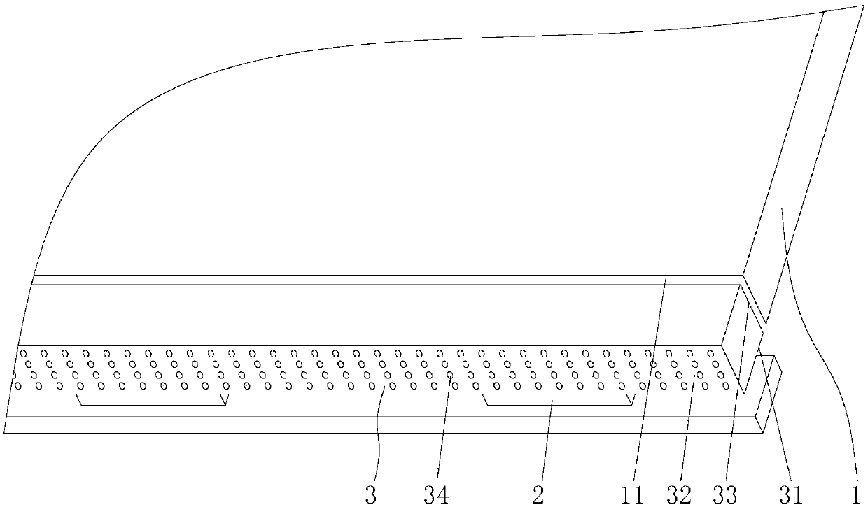
[0013] like figure 2 As shown, the LED light-emitting device of the present invention includes a backlight module, the backlight module includes an LED light source 2 and a light guide plate 1, and it also includes a light guide column 3, and the light guide column 3 includes an incident beam for receiving light beams. Surface 31, a bottom surface 32 connected to the incident surface 31 and an exit surface 33 opposite to the bottom surface 32, the bottom surface 32 is provided with a dot structure 34 for converting the incident light beam into parallel light exit, and the light guide column 3 is set On the light incident side of the light guide plate 1, and the exit surface 33 faces the light guide plate 1, the LED light source 2 is set corresponding to the incident surface 31 of the light guide column 3, and the light beam emitted by the LED light source 2 enters the light guide column 3 from the incident surface 31, passes through the dots After the structure 34 converts th...


PUM


Abstract

The present invention relates to an LED light emitting device comprising a backlight module. The backlight module comprises an LED light source and a light guiding plate. The device further comprisesa light guiding column, and the light guiding column comprises an incident surface for receiving a light beam, a bottom surface connected to the incident surface, and an exit surface opposite to the bottom surface. The bottom surface is provided with a network spot structure for converting an incident light beam into parallel light to send the parallel light out, the light guiding column is arranged on a light incident side of the light guiding plate, and the light exit surface faces the light guiding plate. The LED light source is corresponding to the incident surface of the light guiding column, the light beam emitted by the LED light source enters into the light guiding column from the incident surface, and after the network spot structure converts the incident light beam into the parallel light, the parallel light is emitted into the light incident side of the light guiding plate from the exit surface. The LED light emitting device has the advantages of reasonable design, simple structure and good uniformity of light entering the light guiding plate, the incident light of the backlight module is uniform, a poor Hotspot phenomenon can be eliminated, the design difficulty of light guiding plate network spots is reduced, the number of LEDs is reduced, and the cost is reduced.

Description

technical field [0001] The invention relates to the technical field of liquid crystal displays or LED lighting equipment, in particular to an LED lighting device. Background technique [0002] like figure 1 As shown, the existing backlight module is applied to liquid crystal display or LED lighting equipment, which usually includes a light guide plate 01, and a plurality of LED light sources 02 are arranged on the light incident side 011 of one side of the light guide plate 01, and the light emitted by the LED light source 02 Enter the light guide plate 01 from the light incident side 011 of the light guide plate 01 , and uniformize the light through the light guide plate 01 to form a surface light source. Since the light of the LED enters the light guide plate at a certain angle, there is an angle blind area (that is, a shadow area) between the two LEDs, which will cause obvious firefly (hotspot) in the display area of ​​the liquid crystal display device or LED lighting eq...

Claims


Application Information

Patent Timeline
IPC IPC(8): G02B6/00G02F1/13357F21S8/00F21V8/00F21Y115/10
CPCF21S8/00F21V2200/20F21Y2115/10G02B6/0028G02F1/133606G02F1/133611G02F1/133615G02F1/133607
Inventor 李远征肖慈斌陈芃杉
Owner TPV ELECTRONICS (FUJIAN) CO LTD
Why Eureka
Try Eureka