Universal wire clamp for power line

A power line, general-purpose technology, applied in circuits, electrical components, conductive connections, etc., can solve problems such as inability to apply cables of different diameters, restraint, troublesome disassembly and assembly of wire clips, etc., to improve practicability and versatility , reduce production costs, strengthen the effect of fixed restraint

Active Publication Date: 2019-03-26
安徽顺开电气有限公司
View PDF6 Cites 0 Cited by
  • Summary
  • Abstract
  • Description
  • Claims
  • Application Information

AI Technical Summary

Problems solved by technology

[0004] The purpose of the present invention is to provide a universal clamp for power lines, through the screw through the first straight slot and the second straight slot and cooperate with the nut to make the first cover plate and the second cover plate buckle Fitted on the fixed inner core, so that the cable clamp can fix and bind the cable, and the curvature of the second arc-shaped groove and the third arc-shaped groove is greater than the curvature of the first arc-shaped through groove, so it can be applied to wires of different diameters cable, which solves the problem that the existing cable clips cannot be used for cables of different diameters, which brings a certain amount of trouble to people when disassembling and assembling the cable clips.

Method used


Image

  • Universal wire clamp for power line
  • Universal wire clamp for power line
  • Universal wire clamp for power line

Examples


Embodiment 1

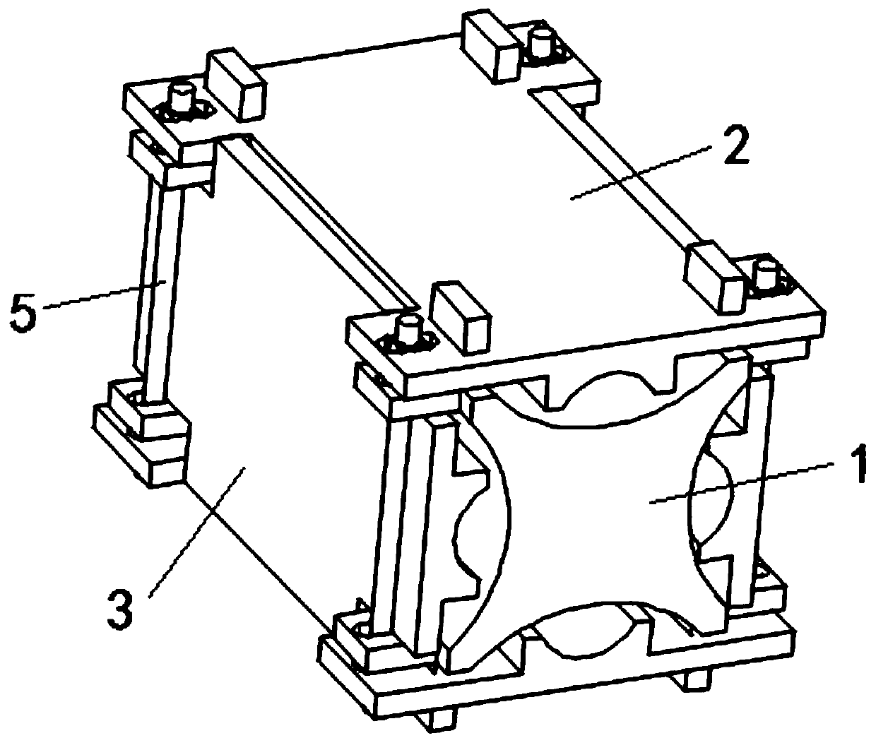
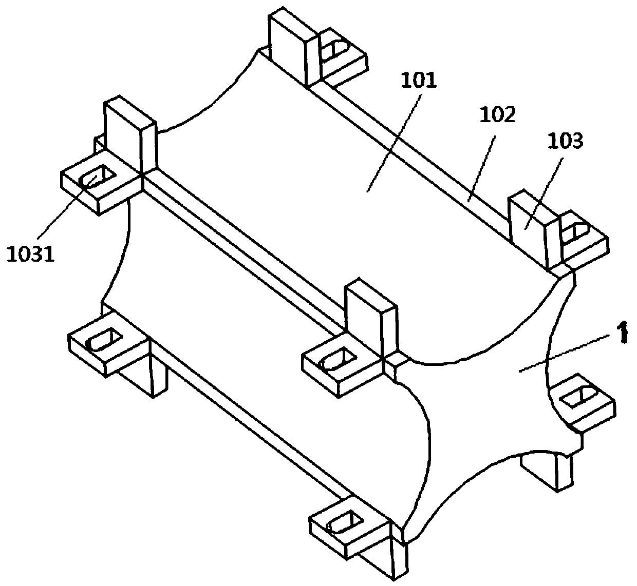
[0035] like Figure 1-2 As shown, the present invention is a general-purpose clamp for power lines, including a fixed inner core 1, a first cover plate 2 and a second cover plate 3, the fixed inner core 1 is a cuboid structure, and the fixed inner core 1 There is a first arc-shaped through groove 101 on the side, and the first arc-shaped through groove 101 makes the side of the fixed inner core 1 form a group of symmetrical strip surfaces 102, and the two ends of the strip-shaped surfaces 102 are symmetrically fixed with ear plates 103 ;

[0036] Wherein, a first straight notch 1031 is formed on the ear plate 103 on an opposite side of the fixed inner core 1, and the length direction of the first straight notch 1031 is parallel to the width direction of the fixed inner core 1;

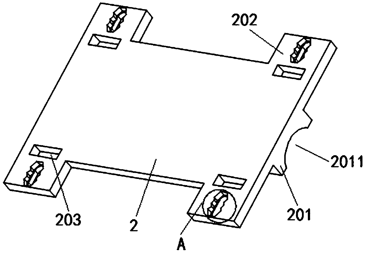
[0037] like Figure 3-6 As shown, both the first cover plate 2 and the second cover plate 3 are of cuboid structure; the lower surface of the first cover plate 2 is fixed with a clamping plate 201; a...

Embodiment 2

[0049] Pass the cable through the gap between the second arc-shaped slot 2011 and the first arc-shaped slot 101 and the gap between the third arc-shaped slot 3011 and the first arc-shaped slot 101, and then clamp the nut on the In the nut slot 2022, use a screwdriver to tighten the screws, so that the two first cover plates 2 are close to each other, and the two second cover plates 3 are close to each other, and finally the cables are clamped and fixed. This process is convenient for disassembly and assembly, and is convenient for people to install. Operation, suitable for cables of different diameters, reducing the cost of people manufacturing plate clamps.


PUM


Abstract

The invention discloses a universal wire clamp for a power line and relates to the technical field of power equipment. The universal wire clamp comprises a fixed inner core, a first cover plate and asecond cover plate. The fixed inner core is a rectangular parallelepiped structure, first curved through grooves are set on side surfaces of the fixed inner core, the first curved through grooves allow side surfaces of the fixed inner core to form a set of symmetrical strip-shaped faces, and ear plates are symmetrically fixed at two ends of the strip-shaped faces, wherein the ear plates on one opposite side surface of the fixed inner core are provided with first straight notches whose length directions are parallel to the width direction of the fixed inner core. According to the invention, screws pass through the first notches and second notches and cooperate with nuts to fasten the first cover plate and the second cover plate to the fixed inner core, therefore, the wire clamp fixes and fastens a cable, the curvature of a second arched groove and a third arched groove is larger than the curvature of the first arched groove, so the wire clamp can be suitable for cables of different diameters, the versatility of the wire clamp is improved, and convenience is brought to installation for people.

Description

technical field [0001] The invention belongs to the technical field of electric equipment, and in particular relates to a universal clamp for electric lines. Background technique [0002] The connection between power lines requires the use of a large number of clamps, and usually it is necessary to fix the cables leading out of the components, so as to avoid the entanglement of multiple bundles of cables, and at the same time prevent the cables from shaking to cause poor contact. At present, the clamps on the market are generally designed for a certain wire diameter. For wires with different wire diameters, multiple sets of wire clamps need to be designed to meet the requirements. When installing wire clamps, when connecting wires with different diameters and fixing cables with different diameters, the staff needs to carry multiple sets of different wire clamps, which brings great inconvenience to the staff. For production enterprises, it is necessary to design multiple set...

Claims


Application Information

Patent Timeline
IPC IPC(8): H01R11/03H01R11/09H01R4/2406H01R4/66
CPCH01R4/2406H01R4/66H01R11/03H01R11/09
Inventor 解山章存春柳庆
Owner 安徽顺开电气有限公司
Why Eureka
Try Eureka