

A device and method for installing a water collector
A water collector and installation device technology, applied in the direction of supporting machines, machine tables/brackets, pipeline brackets, etc., can solve the problem that the supporting frame cannot be adjusted, and achieve the effect of improving versatility and practicability
- Summary
- Abstract
- Description
- Claims
- Application Information
AI Technical Summary
Problems solved by technology
Method used
Image

Examples
Embodiment 1
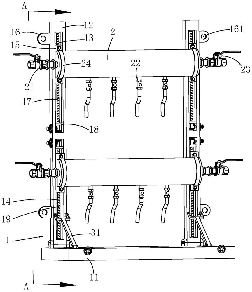
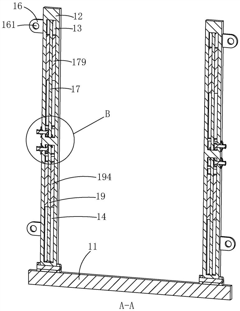
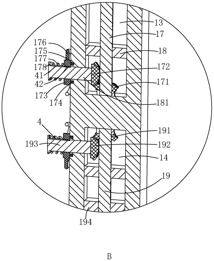
[0045] Such as figure 1 As shown, a water collector installation device includes a mounting bracket 1 and a water collector 2 located on the mounting bracket 1. The mounting bracket 1 includes a support plate 11 and two support rods 12 that are rotatably connected to the support plate 11, and Two support rods 12 are arranged near the side wall of the support plate 11, see Figure 4 There are four sets of evenly distributed first installation holes 111 running through the support plate 11, and the two support rods 12 are arranged symmetrically. Two installation holes 161, the support rod 12 is provided with a first guide chute 13 and a second guide chute 14 along the length direction, the first guide chute 13 is provided with a first bevel gear 171 near the second guide chute 14, The first bevel gear 171 is concentrically provided with a first threaded rod 17, and the first threaded rod 17 is arranged along the length direction of the first guide chute 13, see figure 2 , the...
Embodiment 2
[0050] A method for installing a water collector, comprising the steps of:
[0051] Step 1: Position mark, first place the connection between the support rod 12 and the support plate 11 close to the corner of the wall and the ground, and then use a tape measure or ruler according to the installation position of the support plate 11 and the position of the first installation hole 111 Carry out the measurement, then mark the position to be opened on the ground, then measure by tape measure or ruler according to the installation position of the second mounting hole 161 on the support rod 12, and mark the position to be opened on the wall;
[0052] Step 2: Opening holes, according to the size specifications of the first installation hole 111 and the second installation hole 161, select a suitable drill bit, and use an electric drill to drill holes at the marked positions;
[0053] Step 3: Install the support plate 11, first install the sleeve of the expansion bolt in the hole on t...
PUM
 Abstract
Description
Claims
Application Information