Smart lighting monitoring terminal and system and corresponding monitoring method

A monitoring terminal and smart technology, applied in the field of smart lighting monitoring terminals, can solve the problems of low monitoring accuracy, low monitoring efficiency, and high labor costs, and achieve the effect of intelligent monitoring methods, efficient monitoring, and improved accuracy

Inactive Publication Date: 2019-03-26
ZHANGJIAKOU POWER SUPPLY COMPANY OF STATE GRID JINBEI ELECTRIC POWER COMPANY +1
View PDF5 Cites 0 Cited by
  • Summary
  • Abstract
  • Description
  • Claims
  • Application Information

AI Technical Summary

Problems solved by technology

However, the traditional street lighting monitoring solution adopts manual control, the

Method used


Image

  • Smart lighting monitoring terminal and system and corresponding monitoring method
  • Smart lighting monitoring terminal and system and corresponding monitoring method
  • Smart lighting monitoring terminal and system and corresponding monitoring method

Examples


Embodiment 1

[0049] Embodiment 1 A smart lighting monitoring terminal

[0050] This embodiment provides a smart lighting monitoring terminal 110 .

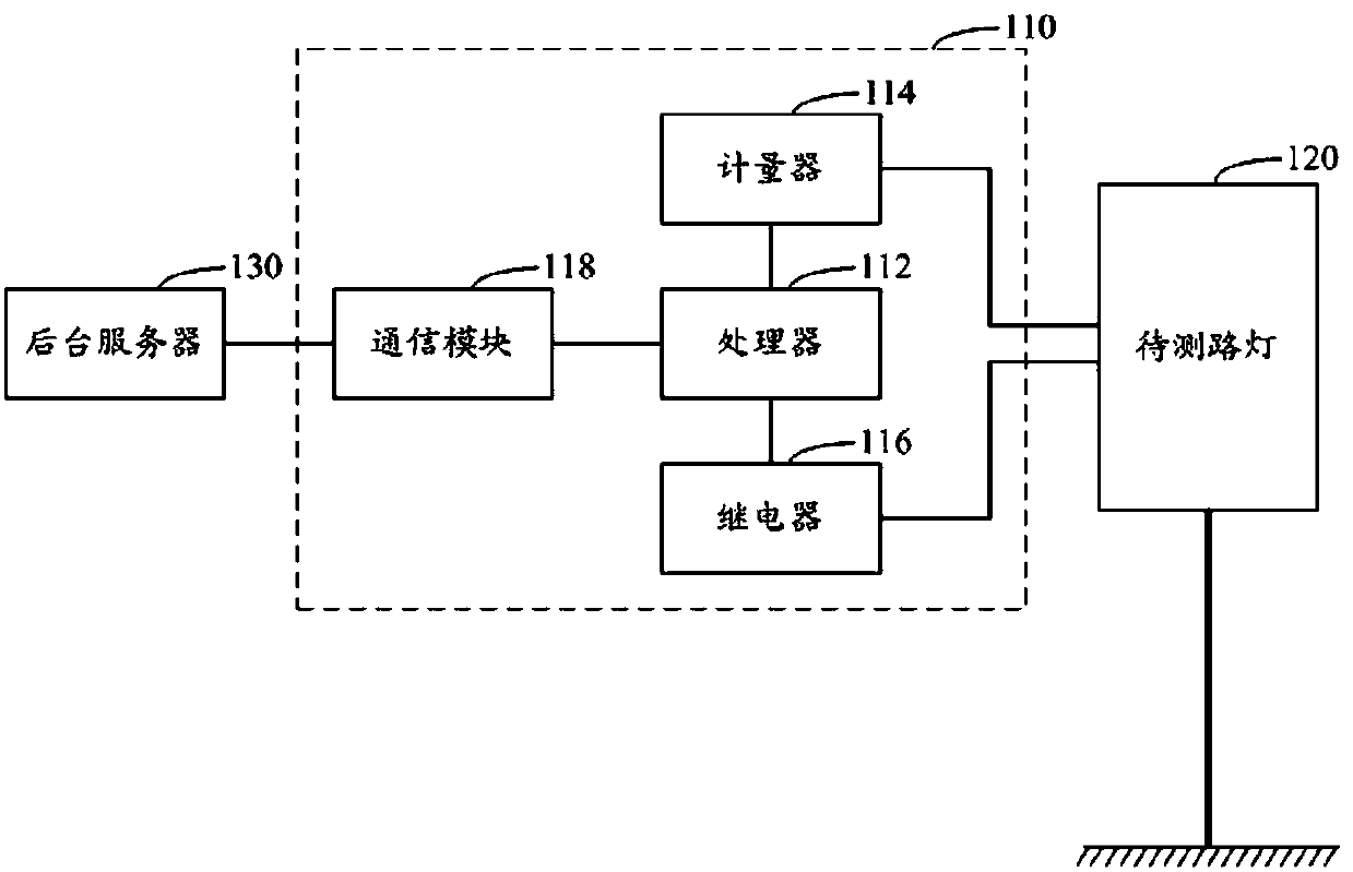
[0051] Such as figure 1 As shown, this embodiment includes a communication module 118, a meter 114, a processor 112 and a relay 116;

[0052] The instruction input end of processor 112 is connected with background server 130 through communication module 118, and the instruction output end of processor 112 is connected with the instruction signal input end of street lamp 120 to be tested through relay 116; 114 is connected with the street lamp 120 to be tested.

[0053] The processor 112 is configured to receive the instruction from the background server 130 received by the communication module 118 and the measurement result of the meter 114 , and send a corresponding control command to the relay 116 .

[0054] Wherein, the processor 112 refers to a device having signal processing and transmission functions. Optionally, the processor 112 ma...

Embodiment 2

[0062] Embodiment 2 An intelligent lighting monitoring system

[0063] Such as Figure 4 As shown, this embodiment includes a background server 130 and at least one embodiment 1. The background server 130 is connected to the processor 112 corresponding to the communication module 118 through the communication module 118 .

[0064] The processor 112 can transmit the processed data (such as the fault data of the street lamp 120 to be tested) to the background server 130 through the communication module 118 . The monitoring status of the smart lighting monitoring terminal 110 and the running status of the corresponding street lamp 120 to be tested are monitored in real time through the background server 130 .

[0065] Preferably, the update data can be transmitted to the processor 112 through the background server 130, so as to implement remote data update of the processor 112.

Embodiment 3

[0066] Embodiment 3 A monitoring method for smart lighting

[0067] This embodiment is realized by using Embodiment 1 or 2, including the following steps carried out in sequence,

[0068] 1. The processor 112 obtains the light control command to be executed sent by the background server 130 through the communication module 118 and identifies the priority level of the light control command to be executed. At the same time, the processor 112 obtains the corresponding street lamp 120 to be tested by measuring The priority level of the currently running light control command;

[0069] 2. The processor 112 compares the priority level of the light control command to be executed and the currently running light control command;

[0070] 3. When the priority level of the light control command to be executed is greater than or equal to the priority level of the currently running light control command, the processor 112 outputs the light control command to be executed to the relay 116 ....


PUM


Abstract

The invention discloses a smart lighting monitoring terminal comprising a communication module, a meter, a processor and a relay. A command input end of the processor is connected to a background server through the communication module, a command output end of the processor is connected to a command signal input end of a street lamp to be tested through the relay, and a street lamp information input end of the processor is connected to the street lamp to be tested through the meter. The invention also discloses a smart lighting monitoring system including the background server and at least onesmart lighting monitoring terminal and a smart lighting monitoring method implemented by using the smart lighting monitoring terminal. Compared with a traditional manual monitoring mode, the monitoring mode of the invention is efficient, intelligent and accurate. The invention is applicable to smart lighting monitoring.

Description

technical field [0001] The invention relates to the technical field of lighting control and is used for realizing intelligent monitoring of street lamps, in particular to an intelligent lighting monitoring terminal, system and corresponding monitoring method. Background technique [0002] As an important infrastructure in every city, road lighting has always played a huge role, bringing great convenience to people's lives. However, the traditional street lighting monitoring solution uses manual control, which has low monitoring efficiency and accuracy, and high labor costs. [0003] With social development and scientific and technological progress, smart lighting is a development trend of urban road lighting. In order to ensure the normal and stable operation of smart lighting, monitoring of smart lighting is essential. Contents of the invention [0004] The purpose of the present invention is to provide a smart lighting monitoring terminal and system for monitoring smar...

Claims


Application Information

Patent Timeline
IPC IPC(8): H05B37/02H05B37/03
CPCH05B47/10H05B47/20Y02B20/40
Inventor 齐火箭王嘉宏李战国郝晓晓张婧张新瑞刘铜锁徐海宾张治国袁慧张捷靖路鑫张志超任志丹陈曦高展许丽丽张旭
Owner ZHANGJIAKOU POWER SUPPLY COMPANY OF STATE GRID JINBEI ELECTRIC POWER COMPANY
Why Eureka
Try Eureka