Surface cleaning base

A surface cleaning and base technology, applied to cleaning equipment, suction nozzles, vacuum cleaners, etc., can solve problems such as insufficient reliability of gas-liquid separation

Pending Publication Date: 2019-03-29
SUZHOU EUP ELECTRIC CO LTD
View PDF3 Cites 4 Cited by
  • Summary
  • Abstract
  • Description
  • Claims
  • Application Information

AI Technical Summary

Problems solved by technology

The accessories in the above two documents both realize the expansion of the scope of use of vacuum cleaners using ordinary dry vacuum motors, but both have shortcomings in the reliability of gas-liquid separation

Method used


Image

  • Surface cleaning base
  • Surface cleaning base
  • Surface cleaning base

Examples


Embodiment Construction

[0026] In order to describe the technical content, structural features, achieved goals and effects of the invention in detail, the following will be described in detail in conjunction with the embodiments shown in the accompanying drawings.

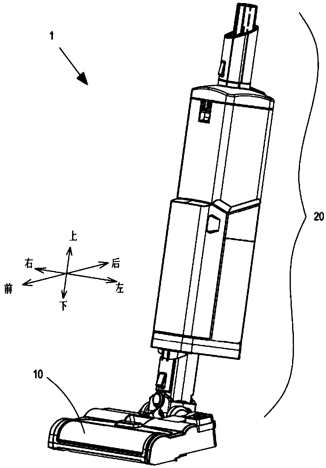
[0027] For purposes of description relative to the figures, the terms "upper", "lower", "right", "left", "rear", "front", "vertical", "horizontal", "inner", "outer" and Its derivative shall refer to the user's perspective from behind the Surface Cleaning Base 1 (e.g. figure 1 orientation shown in ).

[0028] figure 1 is a schematic perspective view of a surface cleaning base 1 attached to a vacuum cleaner for use, which includes a cleaning head 10 adapted to move over the surface to be cleaned and a lower portion rotatably connected to the cleaning head 10 Uprights 20.

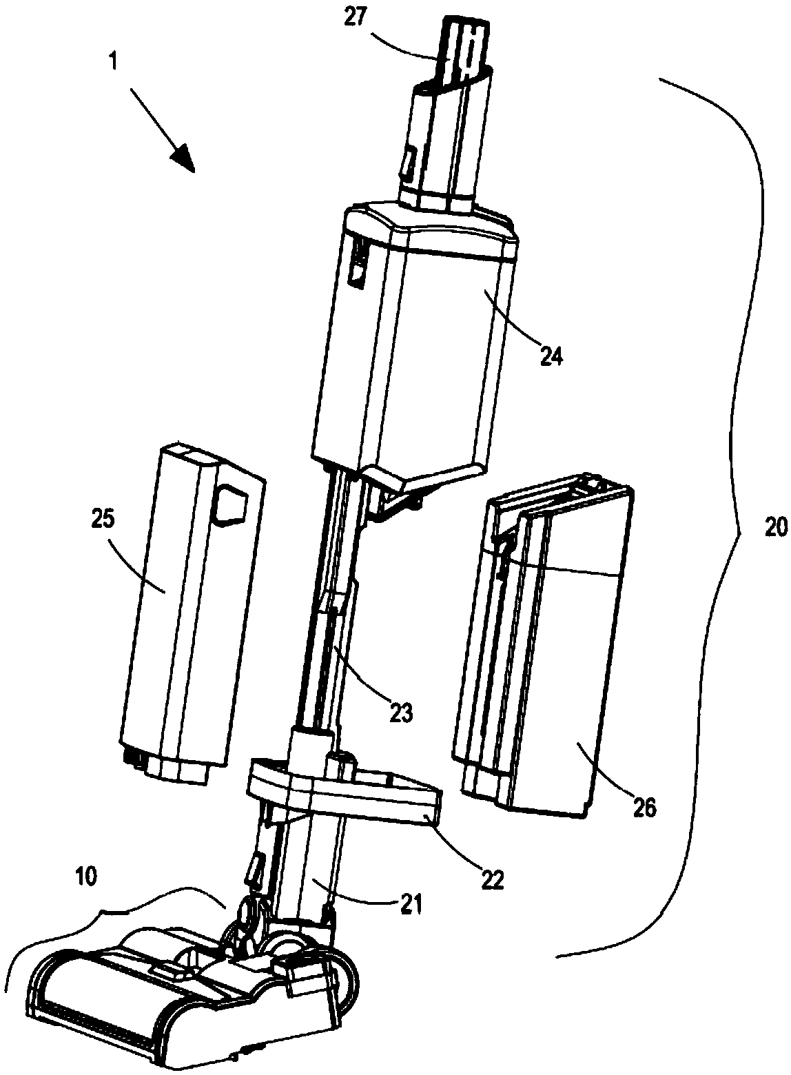
[0029] Such as figure 2 The exploded schematic view of the surface cleaning base 1 shown, the upright part 20 includes a lower connection head 21, a lower support pl...


PUM


Abstract

The invention relates to a surface cleaning base. The surface cleaning base comprises a cleaning head part and an upright part, the cleaning head part is provided with a suction mouth and a spraying mouth, and an air liquid entering chamber, a liquid supplying chamber, a sewage recycle chamber and an air escape chamber are formed in the upright part; a fluid recycle path is arranged between the air liquid entering chamber and the suction mouth, an opening is formed in the bottom of the air liquid entering chamber, a sewage inlet is formed in the upper portion of the sewage recycle chamber, andthe air escape chamber is located on the upper side of the sewage recycle chamber and provided with an air inlet and an air outlet; the sewage inlet is located below the opening, the air inlet is located above the opening, and the sewage inlet, the air inlet and the opening are in fluid communication with one another. A buffer space for air to flow upward is formed among the opening, the sewage inlet and the air inlet. According to the surface cleaning base, the buffer space is formed between the sewage inlet of the sewage recycle chamber and the air inlet of the air escape chamber to have abuffer effect on air which contains sewage droplets, and thus the fluid is effectively prevented from being contained and entering the air escape chamber.

Description

technical field [0001] The present invention relates to the field of vacuum cleaners, and more particularly to a surface cleaning base attached to a vacuum cleaner for wet cleaning of surfaces. Background technique [0002] In the prior art, in order to carry out wet cleaning of the surface to be cleaned, some special wet cleaning equipment is provided. A soil recovery system for fluid and debris (which may include dirt, dust, stains, mud, hair, and other debris). Cleaning fluid delivery systems typically include a supply tank for storing the cleaning fluid, nozzles for applying the cleaning fluid to the surface to be cleaned, and a fluid supply for delivering the cleaning fluid from the tank to the nozzles pipeline. Agitators for agitating the cleaning fluid on the surface are available. The dirty liquid recovery system usually includes a dirty liquid recovery tank, a suction port facing the surface to be cleaned and in fluid communication with the dirty liquid recovery ...

Claims


Application Information

Patent Timeline
IPC IPC(8): A47L5/12A47L9/02
CPCA47L5/12A47L9/02
Inventor 卞庄
Owner SUZHOU EUP ELECTRIC CO LTD
Why Eureka
Try Eureka