Distal fibula C-type bone fracture band lateral wing locking setting structure

A flank and fibula technology, applied in the field of distal fibula type C fracture with flank locking bone structure, can solve the problems of weakened holding force, easy loosening of screws, and influence on treatment effect, so as to improve fixation strength, increase surgical options, and skin tension small effect

Inactive Publication Date: 2019-03-29
CHUANG MEI DE MEDICAL DEVICE TIANJIN CO LTD
View PDF5 Cites 0 Cited by
  • Summary
  • Abstract
  • Description
  • Claims
  • Application Information

AI Technical Summary

Problems solved by technology

[0002] Fracture is one of the most common injuries. With the aging of the population, the annual incidence of fractures is gradually increasing. Fractures of the distal end of the fibula are common fractures. Kirschner wires, tension bands, screws, etc. The stable fixation of the distal end, especially for C-type fractures of the distal end of the fibula, there is no corresponding locking bone plate, and it cannot fully meet the requirements of reduction and fixation
Ordinary bone plates have certain fixation strength, but the conformability cannot be fully satisfied, and complications such as delayed skin healing are prone to occur. However, the existing anatomical bone plates or common locking bone plates do not have multi-angle fixation with screws. The screws are easy to loosen during use, which weakens the holding force, and the screws are easy to hit the articular surface, which makes clinical application difficult, affects the treatment effect, and brings pain to the patient

Method used


Image

  • Distal fibula C-type bone fracture band lateral wing locking setting structure
  • Distal fibula C-type bone fracture band lateral wing locking setting structure
  • Distal fibula C-type bone fracture band lateral wing locking setting structure

Examples


Embodiment Construction

[0016] The technical solution of the present invention will be described in detail below with reference to the drawings and specific embodiments.

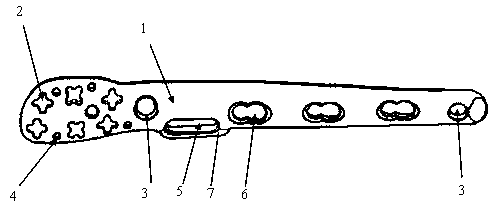
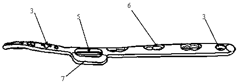
[0017] Such as Figure 1 to Figure 3 As shown, the C-type fracture of the distal end of the fibula with flank locking bone structure of the present invention includes: a locking bone plate 1, a universal locking screw 8, a locking screw and a compression screw 9; The universal locking hole 2, locking hole 3 and guide pin hole 4 of the plate, the stem of the locking bone plate is provided with a side wing 7 protruding to one side, and the side wing is provided with a side wing sliding pressure hole 5 penetrating through the locking bone plate, and the locking bone plate The cadre is also provided with a locking pressure hole 6 and a locking hole 3 that go through the locking bone plate; the universal locking screw, the locking screw and the pressure screw are respectively connected with the universal locking hole, the locking hole, ...


PUM


Abstract

A distal fibula C-type bone fracture band lateral wing locking setting structure including: a bone locking plate, a universal locking screw, a locking screw, and a compressing screw. The head portionof the bone locking plate is provided with a universal locking hole, a locking hole and a needle hole, which penetrate through the bone locking plate. A lateral wing, protruded to one side, is arranged on the body portion of the bone locking plate and is provided with a lateral wing sliding compressing hole which penetrates through the bone locking plate. A locking compression hole and a locking hole are formed in the body portion of the bone locking plate and penetrate through the bone locking plate. The locking screw, on the head portion of the bone locking plate, is fixed in a multidirectional manner so as to keep away from an articular surface, fixing strength being enhanced due to crossed fixation. The bone locking plate fits the fibula of human body and has good fitting ability and less influence on skin tension. By means of the lateral wing sliding compressing hole in the lateral wing, the structure can be fixed by implanting a compressing screw or by elastic structure of buttons and nylon wires, so that the structure is convenient to use in clinical operations.

Description

technical field [0001] The invention relates to the technical field of orthopedic medical devices, in particular to a C-type fracture with lateral wing locking osteosynthesis structure of the distal end of the fibula used for fracture reduction in fracture surgery. technical background [0002] Fracture is one of the most common injuries. With the aging of the population, the annual incidence of fractures is gradually increasing. Fractures of the distal end of the fibula are common fractures. Kirschner wires, tension bands, screws, etc. The stable fixation of the distal end, especially for C-type fractures of the distal fibula, does not have a corresponding locking plate, and cannot fully meet the requirements of reduction and fixation. Ordinary bone plates have certain fixation strength, but the conformability cannot be fully satisfied, and complications such as delayed skin healing are prone to occur. However, the existing anatomical bone plates or common locking bone plat...

Claims


Application Information

Patent Timeline
Patent Type & Authority Applications(China)
IPC IPC(8): A61B17/80
Inventor 潘兵辉林宝颖施忠民洪劲松徐海林
Owner CHUANG MEI DE MEDICAL DEVICE TIANJIN CO LTD
Why Eureka
Try Eureka