Tension mechanism of winding machine

A technology of tension mechanism and winding machine, which is applied in the field of tension mechanism of winding machine, can solve problems such as unstable quality of battery cells, difficult to control tension, S-shaped defects of cells, etc., achieve compact structure, reduce labor costs, good stability effect

Active Publication Date: 2016-08-17
ZHUHAI HIGRAND ELECTRONICS TECH
View PDF8 Cites 0 Cited by
  • Summary
  • Abstract
  • Description
  • Claims
  • Application Information

AI Technical Summary

Problems solved by technology

In the past, the tension control device of the pole piece belt discharge used in the lithium-ion battery winding machine, the roller is fixed on the swing arm, the weight of the swing arm is heavy, and the load of the swing arm of the device increases. During the winding process, the pole piece Due to the large change in the feeding speed of the material belt, the fluctuation range of the tension also increases. The swing range of the swing arm of the device is not stable, and it is difficult to control the small tension. The rolled battery cells are prone to S-shaped Defects, the quality of battery cells is not stable

Method used


Image

  • Tension mechanism of winding machine
  • Tension mechanism of winding machine
  • Tension mechanism of winding machine

Examples


Embodiment Construction

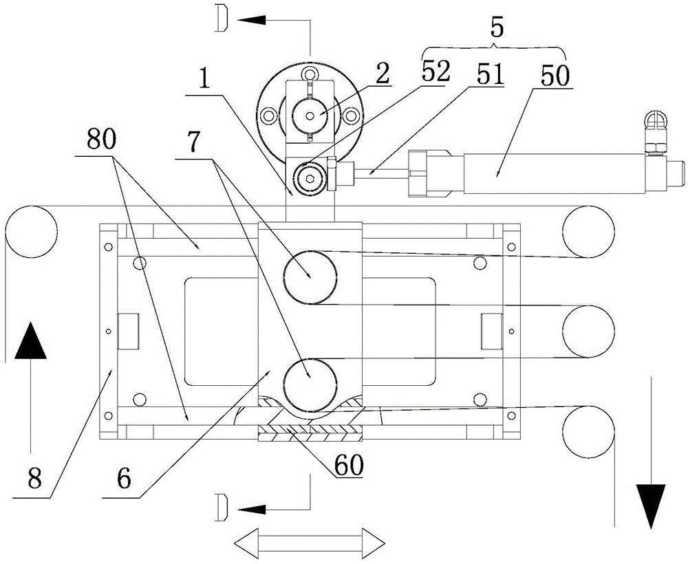
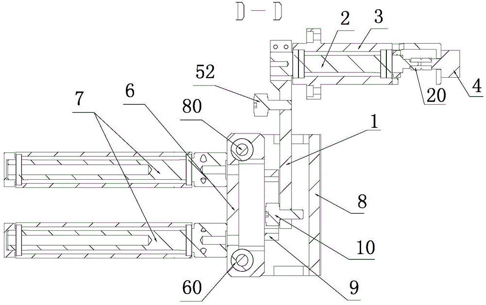
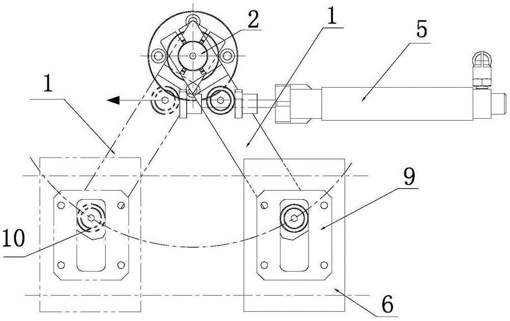
[0016] The tension mechanism of the winding machine, such as Figure 1 to Figure 3 As shown, it is applied to the winding of lithium-ion battery cores. It includes a swing arm 1, a rotating shaft 2, a bearing seat 3, a potentiometer 4 and a constant voltage device 5. The rotating shaft 2 is installed on the body through the bearing seat 3. The swing arm 1 The upper end is fixed on the front end of the rotating shaft 2, and the constant tension device 5 pushes the swing arm 1 at the front end of the rotating shaft 2 to deflect at a certain angle. It is connected with the rotating shaft 2 through a coupling 20; a sliding seat 6 is movably connected to the lower end of the swing arm 1, and two tension rollers 7 arranged parallel to the axis of the rotating shaft 2 are installed on the sliding seat 6. The upper and lower sides of the seat 6 are arranged side by side; the rear side of the sliding seat 6 is provided with a sliding seat frame 8, and the sliding seat frame 8 is provid...


PUM


Abstract

The tension mechanism of the winding machine disclosed by the present invention is applied to winding of lithium-ion battery cores or winding equipment requiring tension control, and it includes a swing arm, a rotating shaft, a bearing seat, a potentiometer and a constant voltage device, and the rotating shaft passes through The bearing seat is installed on the machine body, the upper end of the swing arm is fixed on the front end of the rotating shaft, the constant tension of the constant pressure device pushes the swing arm at the front end of the rotating shaft to deflect at a certain angle, and a potentiometer for monitoring the rotation position of the rotating shaft is installed on the rear side of the bearing seat; The lower end of the swing arm is movably connected with a sliding seat, on which at least one tension roller arranged parallel to the axis of the rotating shaft is installed, a sliding seat frame is arranged on the rear side of the sliding seat, and at least one limiting sliding seat and The tension roller on it moves left and right in parallel with the guide slide bar, and the linear bearing slidingly matched with the guide slide bar is installed on the slide seat.

Description

【Technical field】 [0001] The invention relates to a tension control device, in particular to a tension mechanism of a winding machine. 【Background technique】 [0002] In the field of lithium-ion battery core winding or other processing fields that require tension control, especially in the winding processing of lithium-ion battery cores, the tension control of pole pieces is the key to the quality assurance of lithium-ion battery in the production of lithium-ion battery core winding. It plays a very important role and directly affects the quality of the winding core of the lithium-ion battery, the safety, consistency and service life of the lithium-ion battery. In the past, the tension control device of the pole piece belt unwinding used in the lithium-ion battery winding machine, the roller is fixed on the swing arm, the weight of the swing arm is heavy, and the load of the swing arm of the device increases. During the winding process, the pole piece Due to the large chang...

Claims


Application Information

Patent Timeline
Patent Type & Authority Patents(China)
IPC IPC(8): B65H77/00
Inventor 孙峰李尤祥陈科芝
Owner ZHUHAI HIGRAND ELECTRONICS TECH
Why Eureka
Try Eureka