
Drilling system of glass drilling machine

A drilling machine and glass technology, applied in the direction of stone processing tools, work accessories, manufacturing tools, etc., can solve the problems of inconvenient weight, concentrated force on the glass to be punched, and unfavorable use, so as to facilitate the drilling work and avoid the position Offset, well-designed effects

Active Publication Date: 2019-03-29
泉州台商投资区一创工业设计有限公司
View PDF5 Cites 0 Cited by
  • Summary
  • Abstract
  • Description
  • Claims
  • Application Information

AI Technical Summary

Problems solved by technology

[0003] However, there are deficiencies in the above-mentioned design. The drilling system of the glass drilling machine of the above-mentioned design is inconvenient to limit the position of the glass to be punched when the hole is punched, so that the hole position is prone to deviation, and it is inconvenient to support the glass to be punched. The weight of the holed glass makes the glass to be punched concentrated and prone to breakage, which is not conducive to use. Therefore, we propose a drilling system for a glass drilling machine to solve the above problems

Method used


Image

  • Drilling system of glass drilling machine
  • Drilling system of glass drilling machine
  • Drilling system of glass drilling machine

Examples


Embodiment

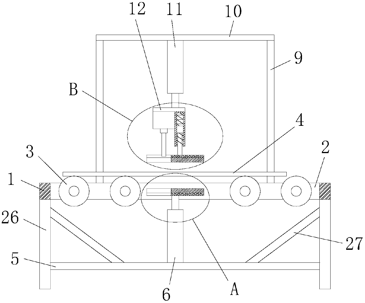
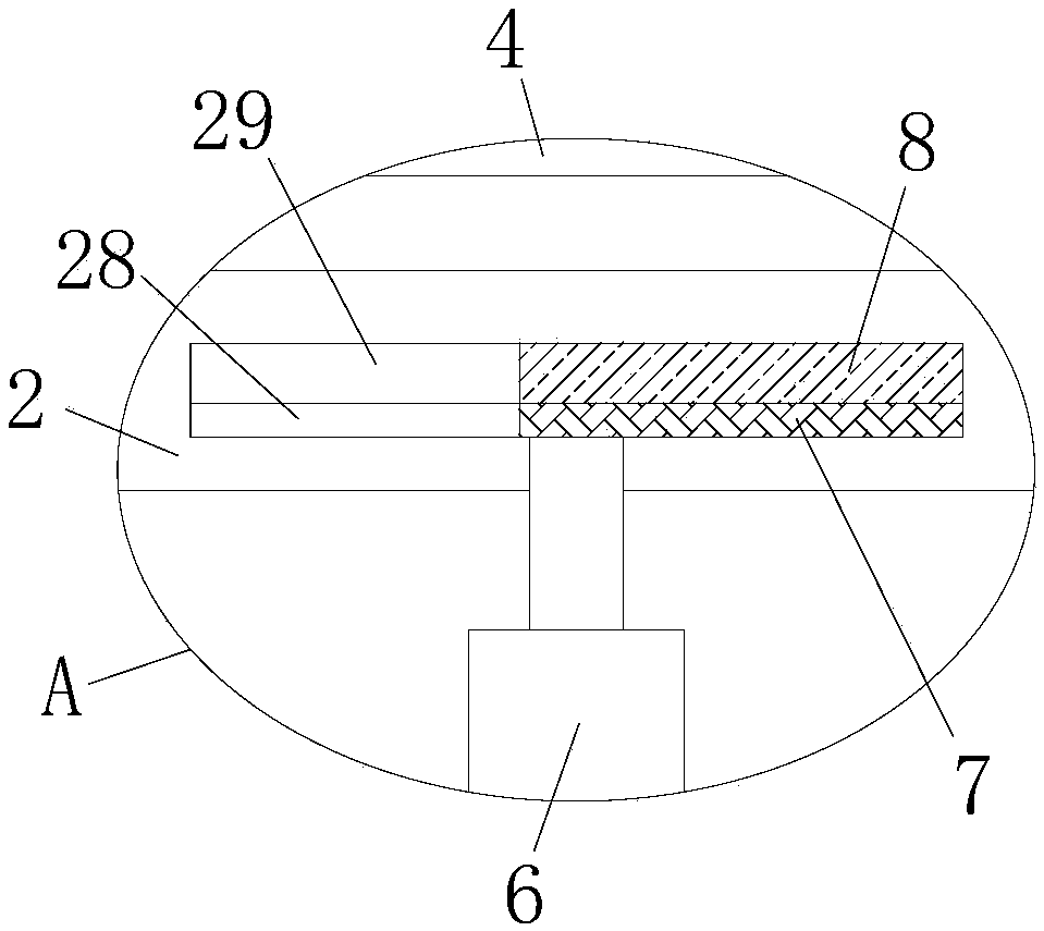
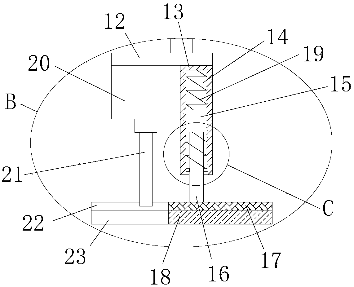
[0029] reference Figure 1-5 In this embodiment, a drilling system for a glass drilling machine is proposed, including a frame 1, a rectangular hole 2 is provided on the top side of the frame 1, and a plurality of glass conveying rollers 3 are rotatably installed on the inside of the rectangular hole 2. And the glass 4 to be drilled is placed on the plurality of glass conveying rollers 3, the four corners of the bottom of the frame 1 are all welded with supporting legs 26, and the side of the four supporting legs 26 close to each other is fixedly connected with the same supporting plate 5. The top of 5 is fixedly connected with a first hydraulic cylinder 6, the output shaft of the first hydraulic cylinder 6 extends into the rectangular hole 2 and is fixedly connected with a first support plate 7, and the top of the first support plate 7 is fixedly pasted with a first rubber pad 8. Two uprights 9 are welded on the top side of the frame 1, and the tops of the two uprights 9 are w...


PUM


Abstract

The invention discloses a drilling system of a glass drilling machine. A rack is included. A rectangular hole is formed in the top side of the rack. A plurality of glass conveying rollers are rotationally arranged on the inner side of the rectangular hole and contain to-be-drilled glass. Supporting legs are welded to the four corners of the bottom of the rack. The sides, getting close to one another, of the four supporting legs are fixedly connected with the same bearing plate. The top of the bearing plate is fixedly connected with a first hydraulic cylinder. An output shaft of the first hydraulic cylinder extends into the rectangular hole and is fixedly connected with a first supporting plate. A first rubber pad is fixedly bonded to the top of the first supporting plate, and two stand columns are welded to one side of the top of the rack. The drilling system is reasonable in design and high in practicability, the first supporting plate can bear the to-be-drilled glass, a second rubberpad can effectively clamp the to-be-drilled glass under the action of elastic force of a first spring, position deflection of the to-be-drilled glass in the punching process is avoided, and the punching work can be better conducted on the to-be-drilled glass.

Description

Technical field [0001] The invention relates to the technical field of glass processing, in particular to a drilling system of a glass drilling machine. Background technique [0002] Glass drilling is one of the important processes in the glass deep processing industry. At present, the main equipment is mainly offline drilling, and most of them are handled manually. There are defects such as high labor intensity, frequent work accidents, insufficient drilling quality, and low output. . After searching, the patent document with application number 201721782272.7 discloses a glass drilling machine drilling mechanism, which has: an upper drilling mechanism, a main bridge structure and a lower drilling mechanism; the main bridge structure includes a bracket, and the upper end of the bracket is provided with a beam; The upper drilling mechanism is connected with the main bridge structure of the lower drilling mechanism; the glass can enter between the upper drilling mechanism and the ...

Claims


Application Information

Patent Timeline
Patent Type & Authority Applications(China)
IPC IPC(8): B28D1/14B28D7/04
CPCB28D1/146B28D7/04
Inventor 罗峰
Owner 泉州台商投资区一创工业设计有限公司
Learn More