
Magnetic automatic bagging machine and use method thereof

A bagging machine and magnetic suction type technology, applied in the field of magnetic suction automatic bagging machines, can solve the problems of easy wrinkling of bags, large workload, low production efficiency, etc., achieve a light and effective bag opening mechanism, and reduce labor fatigue. the effect of improving production efficiency

Pending Publication Date: 2019-03-29
NANJING INST OF TECH
View PDF0 Cites 0 Cited by
  • Summary
  • Abstract
  • Description
  • Claims
  • Application Information

AI Technical Summary

Problems solved by technology

[0002] At present, most of the traditional flexible long wire harnesses with metal ends can only be completed by manual operation, which is time-consuming and labor-intensive, and the production efficiency is low, especially the flexible wire harness that exceeds the length of a human arm, which is expensive and easy to break, so the packaging bag must be cut first. Collaboration is the only way to complete the packaging, the workload is heavy, the efficiency is low, and the bagging is easy to wrinkle due to manual operation, and the quality is unstable

Method used


Image

  • Magnetic automatic bagging machine and use method thereof
  • Magnetic automatic bagging machine and use method thereof
  • Magnetic automatic bagging machine and use method thereof

Examples


Embodiment Construction

[0020] The following will clearly and completely describe the technical solutions in the embodiments of the application with reference to the drawings in the embodiments of the application. Apparently, the described embodiments are only some of the embodiments of the application, not all of them. Based on the embodiments in this application, all other embodiments obtained by persons of ordinary skill in the art without making creative efforts belong to the scope of protection of this application.

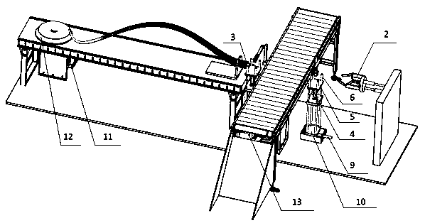
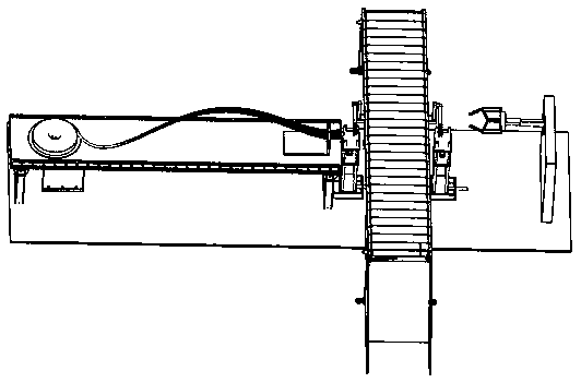
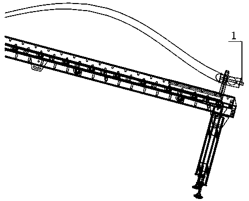
[0021] Such as Figure 1-4 A magnetic suction automatic bagging machine shown includes a workbench, a conveying line, and a cylinder support. Heat-sealing knives 7 and cutting knives 8 are arranged on both sides of the conveying line; slide rails are provided on both sides of the conveying line, and the slide rails pass through the The block 10 is connected to the cylinder bracket, and the cylinder bracket is provided with an ordinary cylinder 9, and the piston rod of the ordinary c...


PUM


Abstract

The invention discloses a magnetic automatic bagging machine. The magnetic automatic bagging machine comprises a mechanical arm, a conveying line, a servo motor, a magnetic bar, a heat sealing knife,a cutting knife, common air cylinders, double acting air cylinders and an infrared counter, wherein the mechanical arm is arranged beside the conveying line, the air cylinders are arranged on the twosides of the conveying line, a workbench is arranged beside the air cylinders, and the magnetic bar and the servo motor are arranged on the workbench; sliding rails are arranged on the two sides of the conveying line, air cylinder supports which can move back and forth between a lifting platform and a conveying line platform are arranged on the sliding rails through sliding blocks, the common aircylinders are installed on the air cylinder supports, piston rods of the common air cylinders are connected with the sliding blocks through connecting pieces, the sliding blocks are connected with thedouble acting air cylinders through fixing plates, bearing plates are connected to the tops of the double acting air cylinders, and a long-line beam is borne by the bearing plates; and a bag openingmechanism is arranged on the workbench and is used for opening a packaging bag. The magnetic automatic bagging machine has the main effects that a large amount of man power can be replaced to realizethe integration of automatic bagging, heat sealing, cutting and counting, thereby greatly improving the working efficiency and reducing the cost.

Description

technical field [0001] The application relates to the field of mechanical engineering, in particular to a magnetic suction automatic bagging machine integrating heat sealing, cutting and counting. Background technique [0002] At present, most of the traditional flexible long wire harnesses with metal ends can only be completed by manual operation, which is time-consuming and labor-intensive, and the production efficiency is low, especially the flexible wire harness that exceeds the length of a human arm, which is expensive and easy to break, so the packaging bag must be cut first. The packaging can only be completed through cooperation, which requires a large workload and low efficiency, and the bagging is easy to wrinkle due to manual operation and the quality is unstable. Contents of the invention [0003] In view of the above problems, the technical problem to be solved in this application is to provide a magnetic suction automatic bagging machine and its use method, t...

Claims


Application Information

Patent Timeline
IPC IPC(8): B65B43/46B65B51/10
CPCB65B43/465B65B51/10
Inventor 任飞颜佳桂
Owner NANJING INST OF TECH
Learn More