Pile-foundation steel reinforcement cage anti-floating device and anti-floating method

A pile foundation steel cage and steel cage technology are applied in sheet pile wall, foundation structure engineering, construction and other directions to achieve the effects of simple structure, good anti-floating effect and low cost

Active Publication Date: 2019-03-29
中建八局广西建设有限公司
View PDF8 Cites 3 Cited by
  • Summary
  • Abstract
  • Description
  • Claims
  • Application Information

AI Technical Summary

Problems solved by technology

[0004] In order to solve the floating problem of uplift piles in deep foundation pit engineering, the invention provides a pile foundation reinforcement cage anti-floating device and anti-floating method

Method used


Image

  • Pile-foundation steel reinforcement cage anti-floating device and anti-floating method
  • Pile-foundation steel reinforcement cage anti-floating device and anti-floating method
  • Pile-foundation steel reinforcement cage anti-floating device and anti-floating method

Examples


Embodiment Construction

[0022] In order to solve the problem of floating uplift piles in deep foundation pit projects, the present invention provides an anti-floating device and an anti-floating method for pile foundation steel cages.

[0023] The preferred embodiments of the anti-floating device and anti-floating method of the pile foundation reinforcement cage of the present invention will be further described below with reference to the drawings and specific embodiments. Those skilled in the art can easily understand other advantages and effects of the present invention from the contents disclosed in this specification.

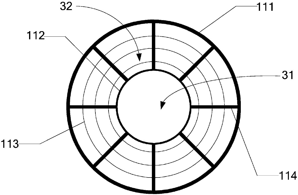
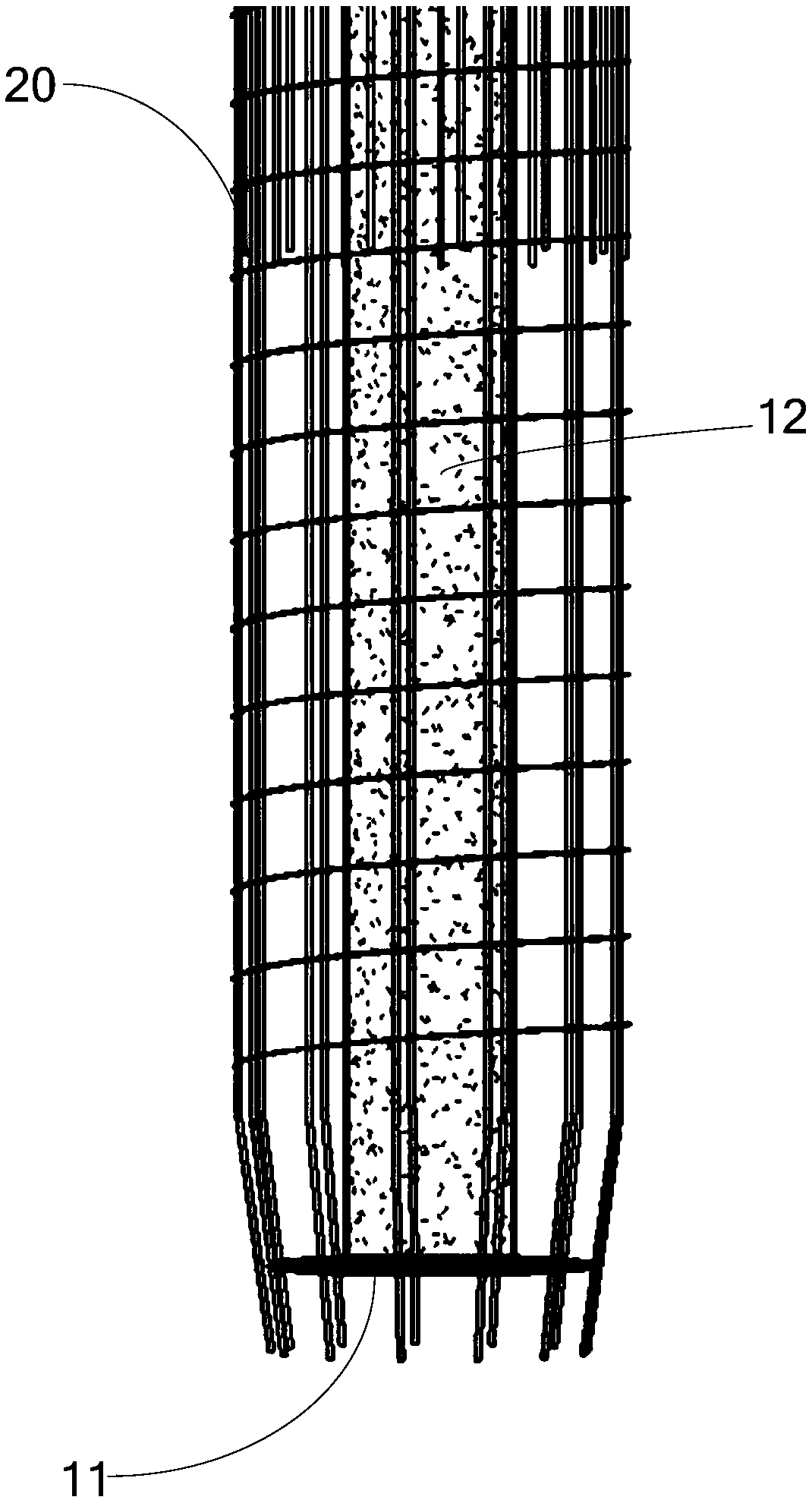
[0024] Combine Figure 1 to Figure 3 As shown, the anti-floating device of the pile foundation reinforcement cage of the present invention includes a leak plate 11 for connecting the reinforcement cage 20 and a grouting hard pipe 12, the grout outlet of the grouting hard pipe 12 is pressed against the leak plate 11, and the leak plate 11 is formed There is a first leakage hole 31 loc...


PUM


Abstract

The invention provides a pile-foundation steel reinforcement cage anti-floating device and anti-floating method. The pile-foundation steel reinforcement cage anti-floating device comprises a leakage plate used for being connected with a steel reinforcement cage and a grouting hard tube, a slurry outlet of the grouting hard tube is pressed against the leakage plate, and a first leakage hole locatedbelow the slurry outlet is formed in the leakage plate. The steel reinforcement cage is subjected to buoyancy, the leakage plate is fixedly connected to the bottom of the steel reinforcement cage, the steel reinforcement cage and the leakage plate are placed into the pile foundation hole together, the grouting hard tube is pressed against the leakage plate, the leakage plate is subjected to downward pressure from the grouting hard tube, the leakage plate is fixedly connected to the bottom of the steel reinforcement cage so as to applying the downward pulling force to the steel reinforcement cage, the pulling force is used for counteracting the buoyancy, and therefore the steel reinforcement cage can be prevented from floating. The grouting hard tube can also be used for pouring concrete in subsequent engineering, the first leakage hole is formed below the slurry outlet, and therefore the leakage plate cannot influence the flow of the concrete, and normal construction of the construction can be guaranteed. According to the pile-foundation steel reinforcement cage anti-floating device and anti-floating method, the structure is simple, necessary facilities for pile-foundation construction are fully utilized, the cost is low, and the anti-floating effect is good.

Description

Technical field [0001] The invention relates to the field of pile foundation engineering construction, in particular to an anti-floating device and an anti-floating method of a pile foundation steel cage. Background technique [0002] During the construction of the pile foundation concrete pouring, the small steel cage, light weight, fast concrete pouring speed, and large buried depth of the conduit will cause the steel cage to float up. For conventional pile foundations, when the pile head is close to the ground or the steel protective tube, the pile head reinforcement can be welded to the steel protective tube or other counter-pressure measures to fix it to avoid the reinforcement cage from floating during the pouring process. However, for the uplift piles of subway stations and deep foundation pits for some houses, construction cannot be carried out after excavation to the bottom of the foundation pit, and construction must be carried out on the original ground. The empty pil...

Claims


Application Information

Patent Timeline
Patent Type & Authority Applications(China)
IPC IPC(8): E02D5/34
CPCE02D5/34
Inventor 范波梁亚华赵维杨永华兰万全戴景轩
Owner 中建八局广西建设有限公司
Why Eureka
Try Eureka