Back alignment sighting device for optics and sighting implementation method
A realization method and sight technology, applied in the field of sights, can solve the problems of high cost of optical sights and difficulty in liberating the eyes, and achieve the effects of high accuracy, high aiming efficiency, and improved precision
- Summary
- Abstract
- Description
- Claims
- Application Information
AI Technical Summary
Problems solved by technology
Method used
Image

Examples
Embodiment 1
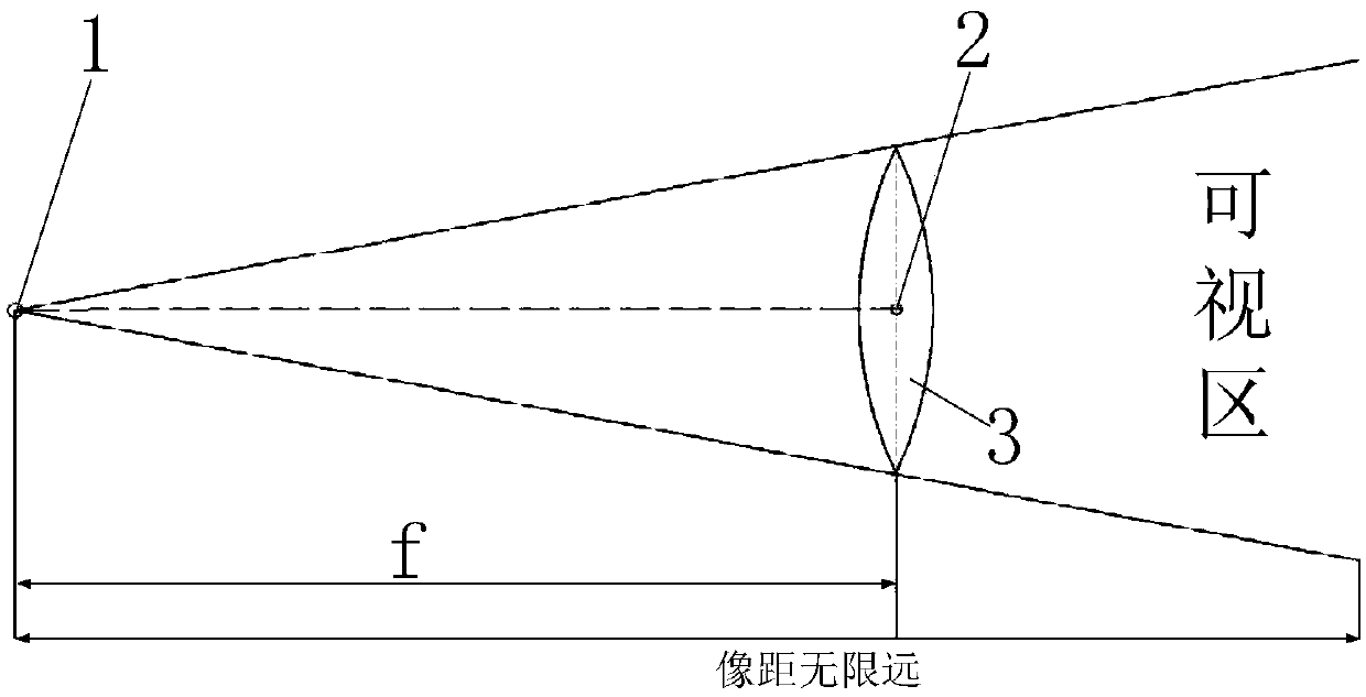
[0073] Such as figure 1 As shown, a method for realizing optical post-collimation aiming includes the steps of: placing the light source 1 near the focal point of the positive lens 3, taking the line distance between the center of the light source and the optical center 2 of the positive lens as the aiming baseline, when the light source When one side of the light source faces the target, the light emitted from the other side of the light source passes through the positive lens to generate aiming light, and the aiming light is aimed at the target to achieve aiming.
[0074] Such as figure 1 As shown, a method for realizing optical post-collimation aiming includes the steps of: placing the light source close to the focal point of the positive lens, and taking the line distance between the center of the light source and the optical center of the positive lens as the aiming baseline;
[0075] Placing the light source near the focal point of the positive lens includes two meaning...
Embodiment 2
[0082] This embodiment provides a preferred implementation of the implementation method of the present invention.
[0083] Such as figure 1 Shown, a kind of realization method of optical post-collimation aiming specifically includes the steps: A, build aiming baseline: connect the optical center of the positive lens and the center of the light source into a line, make the center of the light emitted by the light source and the light The distance between the centers is equal to the focal length f of the positive lens; the distance between the optical center of the positive lens and the light source constitutes the aiming baseline;
[0084] When actually setting the light source, the light source itself has a volume. In order to achieve better aiming accuracy, the position of the light source needs to be adjusted; the center of the light emitted by the light source is best at the focus of the positive lens, so as to meet the requirements of the light source. The distance betwee...
Embodiment 3
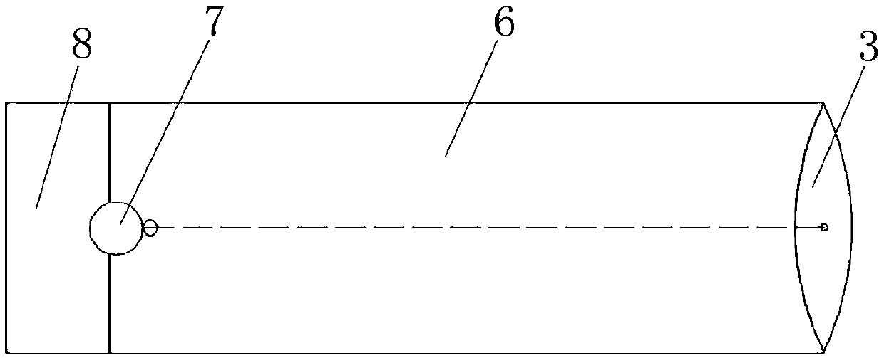
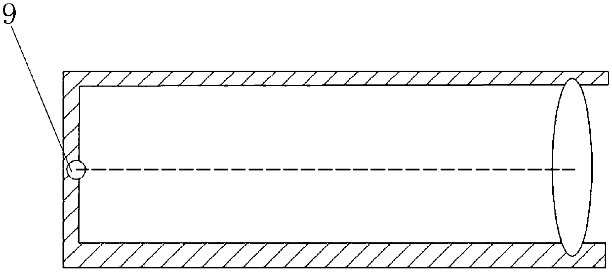
[0092] Such as Figure 2-7 As shown, an optical rear collimation sight includes a sight body; the sight body includes a light source, a positive lens and a lens barrel with an opening on one side; a positive lens is provided on one side of the lens barrel; The other side of the lens barrel is provided with a light source; the light source is located near the focal point of the positive lens; the center of the light source and the optical center of the positive lens are on the same straight line, and when the other side of the lens barrel faces the target, The light emitted by the light source passes through the positive lens to generate aiming light, and the aiming light is aimed at the target to achieve aiming.
[0093] Such as Figure 2-7 Shown, a kind of optical rear collimating sight; Comprising a sight body; The sight body includes a light source 1, a positive lens 3 and a lens barrel 6 with a right opening; a positive lens 3 is arranged on the right opening of the lens ...
PUM
 Abstract
Description
Claims
Application Information
 - R&D Engineer
- R&D Manager
- IP Professional
- Industry Leading Data Capabilities
- Powerful AI technology
- Patent DNA Extraction
Browse by: Latest US Patents, China's latest patents, Technical Efficacy Thesaurus, Application Domain, Technology Topic.
© 2024 PatSnap. All rights reserved.Legal|Privacy policy|Modern Slavery Act Transparency Statement|Sitemap