
High-precision probe clamping device for sampling positioning in neutron diffraction measurement

A technology for sample positioning and clamping device, applied in measurement devices, material analysis using wave/particle radiation, and force measurement, etc., can solve problems such as easy deformation and breakage, waste of neutron beam time, and increased preparation time, etc. Achieve the effect of improving positioning accuracy, improving efficiency and ensuring coaxiality

Pending Publication Date: 2019-03-29
CENT SOUTH UNIV
View PDF19 Cites 5 Cited by
  • Summary
  • Abstract
  • Description
  • Claims
  • Application Information

AI Technical Summary

Problems solved by technology

[0006] In different experimental environments, it is necessary to use probes of different diameters and materials to calibrate the origin of diffraction measurement, and the probes currently used are installed using the same integrated clamping method as the sample fixture, and the position after one installation It cannot be adjusted, and there is a problem of cumbersome probe replacement in the actual operation process. In addition, because the probe has a large length-to-diameter ratio and is fixed at one end while the other end is suspended, it is easy to deform and break.
If the probe needs to be replaced frequently or the probe is broken during the experiment, it will seriously affect the progress of the experiment, greatly increase the preparation time of the experiment, and lead to a serious waste of precious neutron beam time, resulting in huge economic losses
At the same time, in the above probe-based sample positioning method, the installation accuracy and verticality of the probe must be guaranteed at all times, which puts high demands on the clamping and replacement process of the probe

Method used


Image

  • High-precision probe clamping device for sampling positioning in neutron diffraction measurement
  • High-precision probe clamping device for sampling positioning in neutron diffraction measurement
  • High-precision probe clamping device for sampling positioning in neutron diffraction measurement

Examples


Embodiment 1

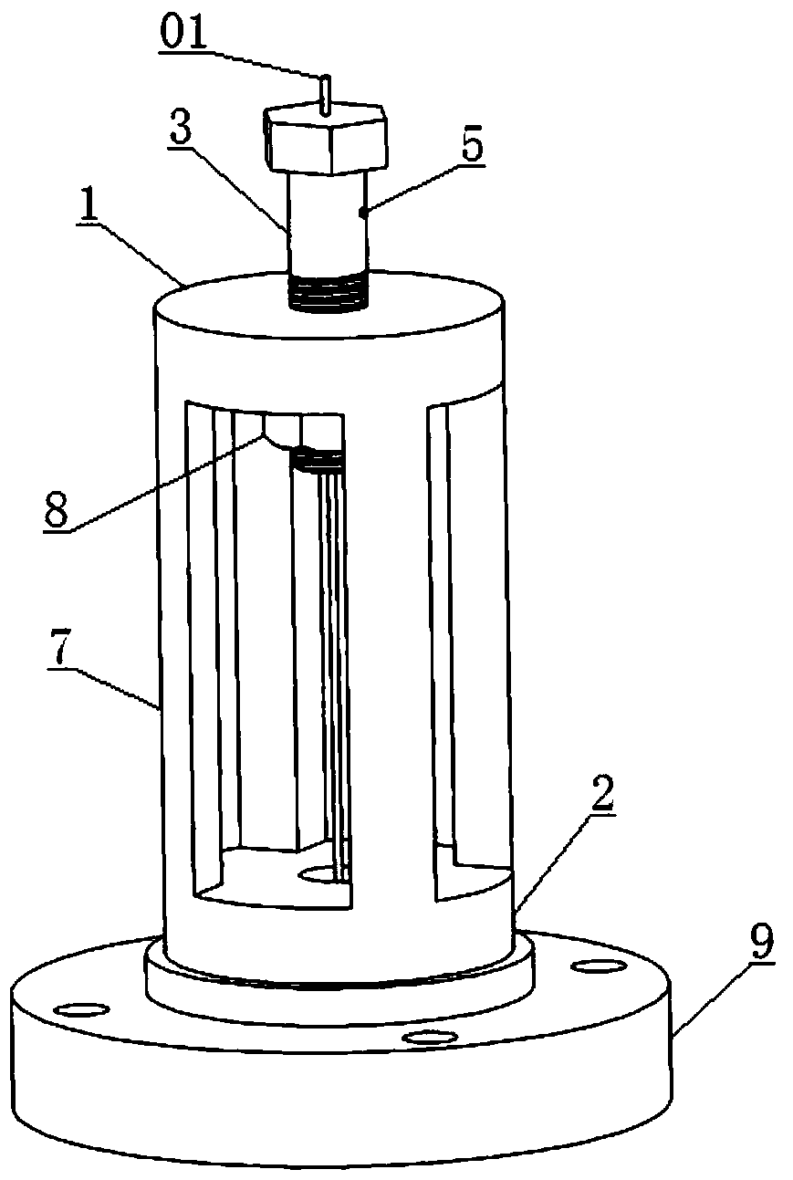
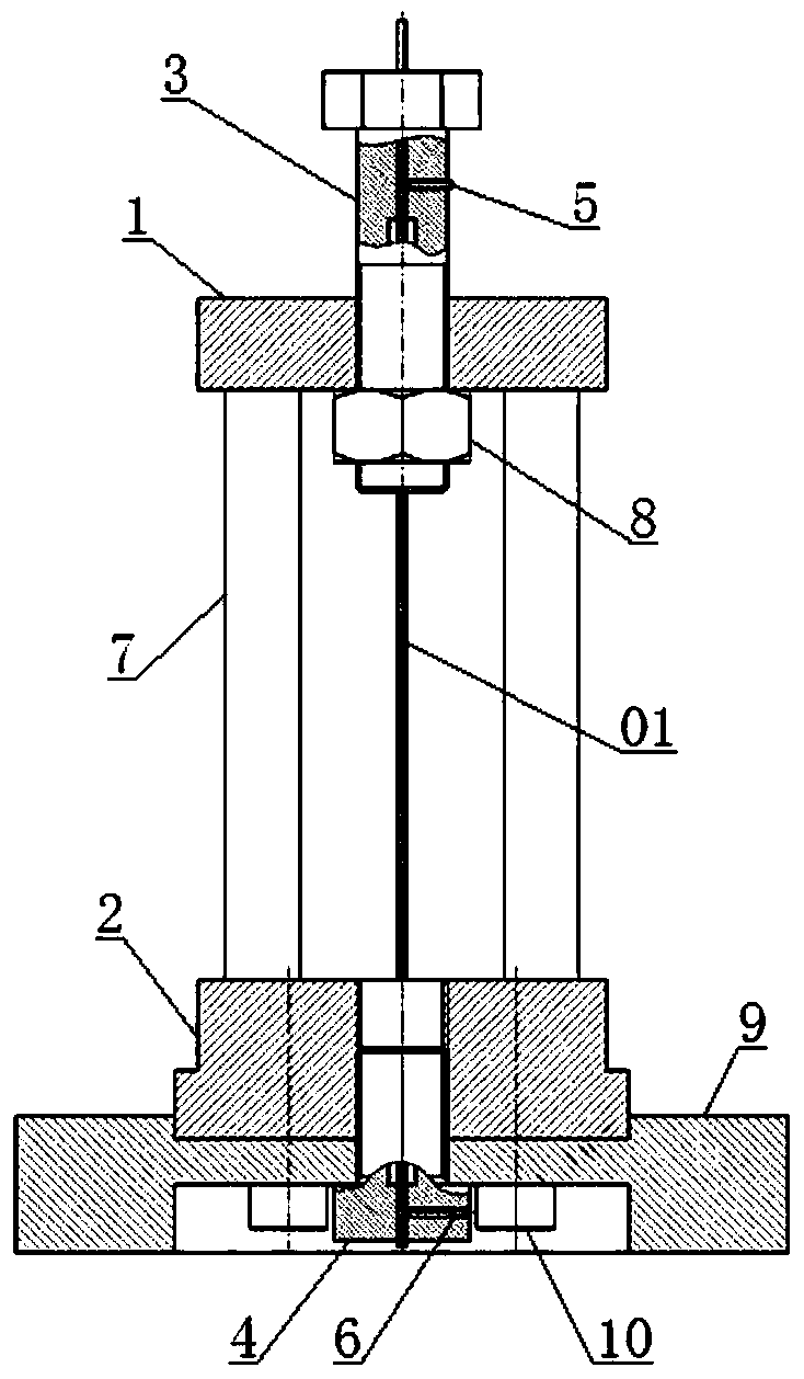
[0036] see figure 1 and figure 2 , a high-precision probe clamping device for sample positioning in neutron diffraction measurement, including a top plate 1, a base 2, an upper positioning member 3, a lower positioning member 4, an upper fastening screw 5, a lower fastening screw 6 and Attach chassis 9.

[0037] The base 2 is arranged at the central position of the connecting chassis 9 and the two are fixedly connected by interference fit and connecting screws 10, and a plurality of screws are arranged on the connecting chassis 9 to realize the fixing between it and the sample stage 02. connected bolt connection holes, the top plate 1 is arranged directly above the base 2 and a vertical support connecting column 7 is arranged between them, and the upper positioning member 3 and the lower positioning member 4 are respectively arranged on the top plate 1 and the base 2 and the distance between the two positioning pieces in the vertical direction is adjustable, and the center ...

Embodiment 2

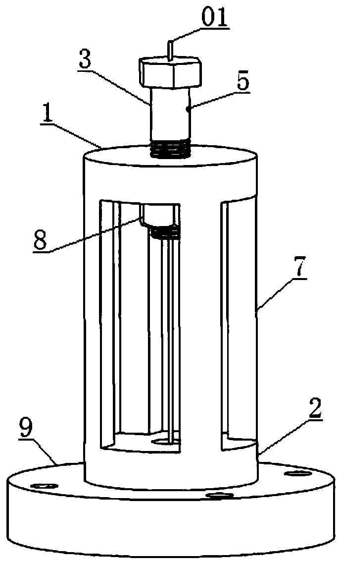
[0041] see image 3 and Figure 4 , a high-precision probe clamping device for sample positioning in neutron diffraction measurement, except that the connecting screw 10 is eliminated between the base 2 and the connecting chassis 9 and the integral molding method is adopted, the other structures are exactly the same as in Example 1 .

Embodiment 3

[0043] see Figure 5 and Figure 6 , a high-precision probe clamping device used for sample positioning in neutron diffraction measurement, its structure is basically the same as that of Embodiment 1, the differences are as follows: In this embodiment, the supporting connecting column 7 and the top plate 1 and the base 2 are connected in a detachable manner, specifically, the two ends of the supporting connecting column 7 are designed in the form of bolts and are respectively fixedly connected to the top plate 1 and the base 2 through matching nuts or threaded holes; The example does not include the connection chassis 9, so there is no need for connection screws 10, the base 2 is directly fixed on the sample stage 02 of the neutron diffraction spectrometer and is provided with a plurality of bolt connection holes on the base 2; in this embodiment, The threaded ends of the two locating parts are set downwards, and matching gaskets and adjusting nuts 8 are provided on the threa...


PUM


Abstract

The invention provides a high-precision probe clamping device for sampling positioning in neutron diffraction measurement. The device comprises a top plate, a base, a plurality of support connection columns, an upper positioning member and a lower positioning member, wherein the top plate and the base are arranged up and down; the support connection columns are vertically arranged between the topplate and the base; the upper positioning member and the lower positioning member are respectively arranged at center positions of the top plate and the base; coaxial and uni-diameter through holes are formed in the two positioning members to contain the upper and lower ends of a probe; a threaded hole matched with a fastening screw and communicated with the through hole in the corresponding positioning member is arranged on each positioning member; the threaded holes are horizontally arranged and located on the same side of the probe; through screw-in and screw-out of the fastening bolts, thetwo ends of the probe are clamped and loosened; and through rotating the positioning members along the thread direction to adjust the distance between the two positioning members, the straightening of the probe is realized. The device is capable of realizing rapid change and straightening operations for the probe under the premise of ensuring the mounting precision and verticality of the probe; and the probe is high in mounting precision and is beneficial for accurate positioning of samples.

Description

technical field [0001] The invention relates to the technical field of neutron diffraction residual stress detection, in particular to a probe clamping device, which is used for sample positioning when neutron diffraction is used to measure the residual stress of materials and components. Background technique [0002] The rapid development of the country is inseparable from the support of the engineering field. Nowadays, the use of large components in various engineering projects has become more and more widespread and frequent, and once a safety accident occurs due to damage to large components, the loss in terms of manpower and material resources will be huge. [0003] According to relevant research, residual stress is one of the important factors that cause local or global failure of materials and components. At present, the methods that can detect the residual stress inside the component are mainly divided into destructive testing method and non-destructive testing meth...

Claims


Application Information

Patent Timeline
Patent Type & Authority Applications(China)
IPC IPC(8): G01N23/20025G01L5/00G01L1/25
CPCG01L1/25G01L5/0047G01N23/20025G01N2223/056G01N2223/106G01N2223/309Y02E30/30
Inventor 李群明邓华张绪烨
Owner CENT SOUTH UNIV
Learn More