Element antenna phase center measuring method in array based on compact range

A phase center, unit antenna technology, applied in measurement devices, antenna radiation patterns, measurement of electrical variables, etc., to achieve the effect of measurement efficiency advantages

Active Publication Date: 2019-03-29
BEIHANG UNIV
View PDF18 Cites 6 Cited by
  • Summary
  • Abstract
  • Description
  • Claims
  • Application Information

AI Technical Summary

Problems solved by technology

Compared with the far-field phase comparison method, the near-field moving reference point method does not require the far-field measurement environment and site, but still requires and requires the phase of the antenna under test to be directly measurable, and the antenna under test needs to be repeatedly translated and rotated during the measurement process

Method used


Image

  • Element antenna phase center measuring method in array based on compact range
  • Element antenna phase center measuring method in array based on compact range
  • Element antenna phase center measuring method in array based on compact range

Examples


Embodiment Construction

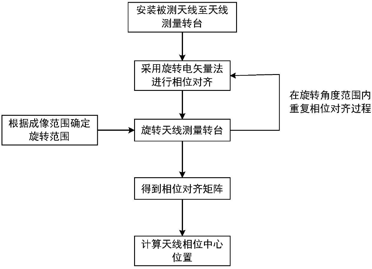
[0024] The present invention will be described below in conjunction with the accompanying drawings and embodiments. The entire execution steps are as follows image 3 Shown, first. Install the antenna under test, then use the rotating electric vector method for phase alignment, then turn the antenna measurement turntable and repeat the rotating electric vector method, and finally calculate the phase center position of the unit antenna in the antenna under test based on the phase alignment data.

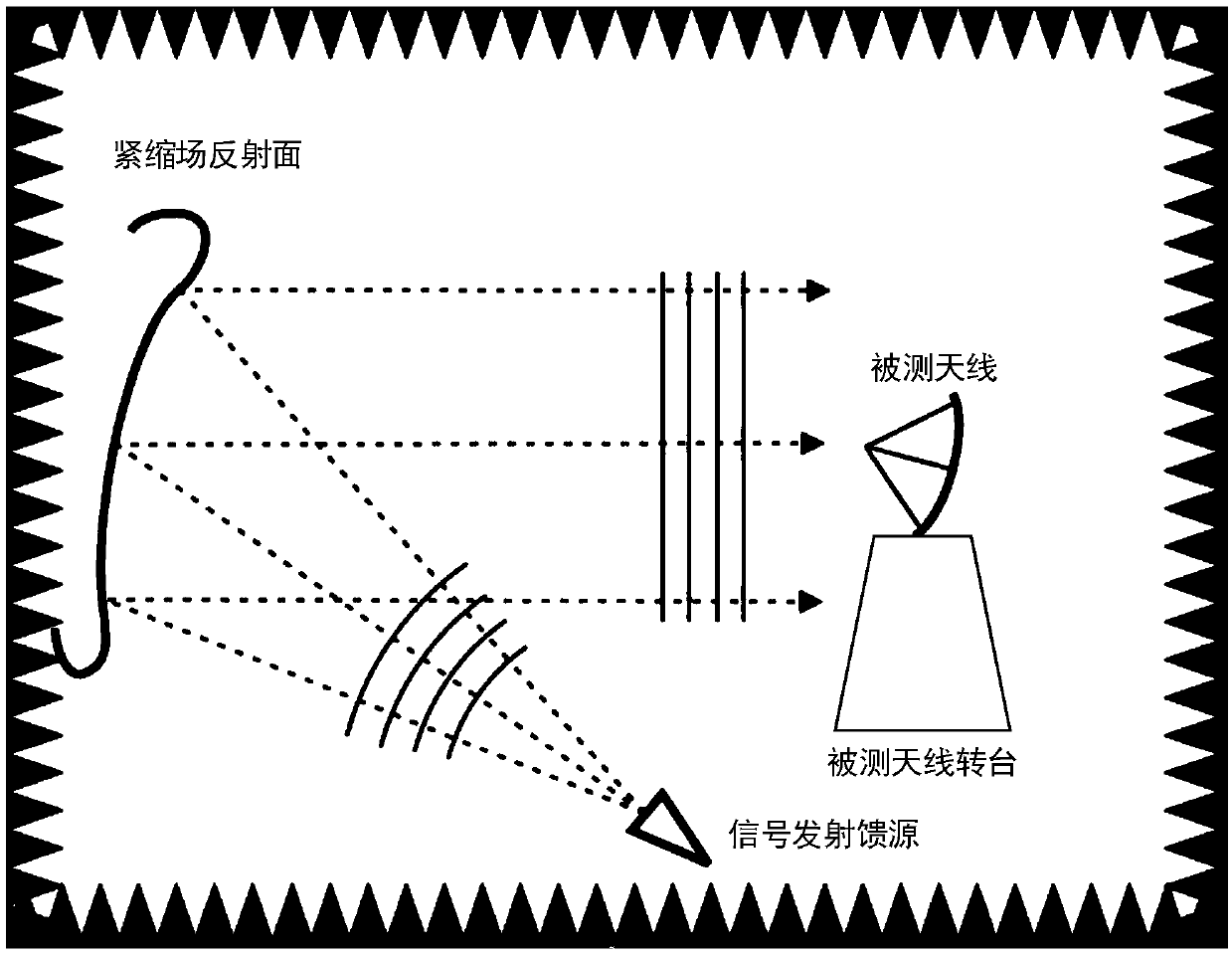
[0025] Such as figure 1 As shown, according to the first step of the present invention, the antenna under test and the signal transmitting feed are installed in a compact field. In the example, the antenna under test is a one-dimensional antenna array composed of 16 unit antennas. Change the phase increment Δ of channel 1 sequentially with 1° step in the range of 0~360° 1 , at this time Δ 1 It is the phase value that channel 1 needs to compensate, and the computer-controlled phas...


PUM


Abstract

The invention provides an element antenna phase center measuring method in an antenna array. The method is characterized in that a converting relation between a phase center position in the compact range and the phase difference among elements in the array and a relation between an array output power which is directly measured through the compact range and the phase difference among the elements in the array are derived; furthermore the compact range is used for directly measuring an array antenna combined output power; deriving the phase difference between unit antennae in the array accordingto a measuring result and further deriving a unit phase central position in the array. Through the measuring method of the invention, the phase center position of the unit antenna in the array can bemeasured.

Description

technical field [0001] The invention relates to the measurement of the phase center of the unit antenna in the array, in particular, a method for measuring the phase center of the unit antenna in the array based on the compact field. Background technique [0002] Array antennas are mainly used for beamforming or synthetic aperture imaging to meet the needs of fast and high-precision imaging. Determining the phase center of the element antenna in the array is a necessary condition for realizing high-precision array beam focusing. Usually, the antenna phase center is not on the antenna face, and it will change as the antenna direction angle increases. For array antennas, the position of the phase center of the antenna will further change due to the mutual coupling of other elements around the antenna in the array. When focusing or imaging the near-field beam of the array, in order to perform accurate phase compensation, it is necessary to obtain the distance between the ante...

Claims


Application Information

Patent Timeline
Patent Type & Authority Applications(China)
IPC IPC(8): G01R29/08G01R29/10
CPCG01R29/0871G01R29/10
Inventor 苗俊刚胡岸勇刘凯
Owner BEIHANG UNIV
Why Eureka
Try Eureka