
High speed differential signal connector

A signal connector, high-speed differential technology, applied in the direction of connection, two-part connection device, parts of the connection device, etc., can solve the problem of large signal return path, shorten the return path, reduce signal crosstalk, and reduce mutual interference Effect

Pending Publication Date: 2019-03-29
SICHUAN HUAFENG ENTERPRISE GRP
View PDF10 Cites 2 Cited by
  • Summary
  • Abstract
  • Description
  • Claims
  • Application Information

AI Technical Summary

Problems solved by technology

[0004] The purpose of the present invention is to provide a high-speed differential signal connector to solve the problem of large return paths between signal pairs in the current high-speed differential signal connectors because the female signal transmission module does not have a shielding plate

Method used


Image

  • High speed differential signal connector
  • High speed differential signal connector
  • High speed differential signal connector

Examples


Embodiment Construction

[0036] In order to make the object, technical solution and advantages of the present invention clearer, the present invention will be further described in detail below in conjunction with the accompanying drawings and embodiments. It should be understood that the specific embodiments described here are only used to explain the present invention, not to limit the present invention.

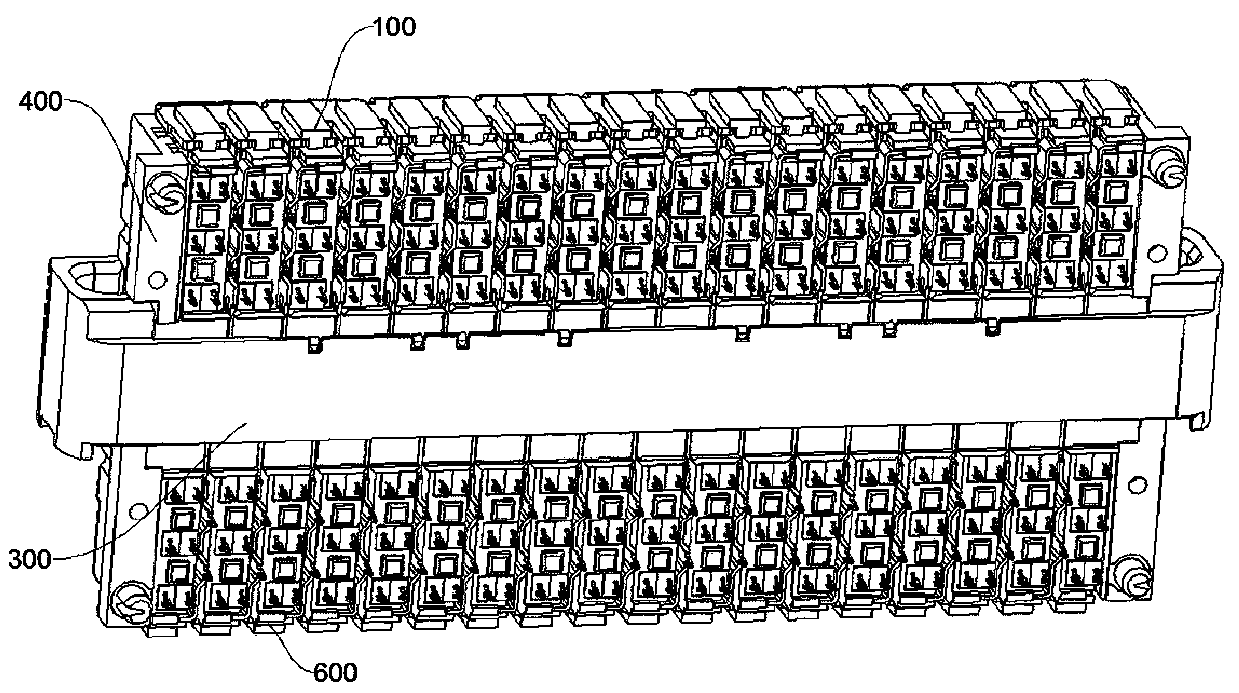
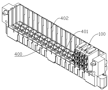
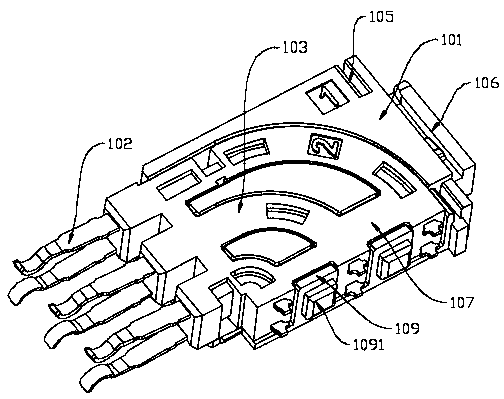
[0037] For an embodiment of the present invention, refer to Figure 1~4 ,exist figure 1 A schematic diagram of the overall structure of a high-speed differential connector is shown in , for this kind of high-speed differential signal connector, it includes a male end connector and a female end connector that are mated with each other, and the above-mentioned female end connector includes a female end base 400 and A plurality of female signal transmission modules plugged in parallel on the female base 400 , through the mating of the male connector and the female connector, enables this high-speed d...


PUM


Abstract

The invention discloses a high speed differential signal connector. The high speed differential signal connector includes a male end connector and a female end connector that are in mutual plug fit; the female end connector includes a female end base and a plurality of female end signal transmission modules that are plugged in parallel on the female end base; each of the female end signal transmission modules includes a signal transmission module and a metal shield plate fixed on the signal transmission module; the lower end portion of the metal shield plate is provided with protruding teeth for fixing and conducting with the female end base; and convex hull structures are disposed on the female end base corresponding to the protruding teeth. In the high speed differential signal connector, the protruding teeth are disposed at the lower end portion of the metal shield plate, and at the same time, the matching convex hull structures are disposed on the female end base to facilitate fixation of the female end signal transmission modules and the metal shield plates, and at the same time, the metal shield plates can communicate with the female end base to form a relatively short backflow path, thus facilitating shortening the backflow path of a differential signal.

Description

technical field [0001] The invention relates to the technical field of connectors, in particular to a high-speed differential signal connector. Background technique [0002] At present, in high-speed differential signal connectors, the return path around the differential signal in the transmission link is realized by multi-point connection to shorten the return path and through the interconnection between metal shields. The distance between metal and metal needs to be kept consistent. Other structures have complex processes and are difficult to control. [0003] In the current high-speed differential signal connector, due to the limitation of its structure, the crosstalk between signals is serious, and the differential signals interfere with each other, which ultimately affects the transmission effect of the signal connector. Contents of the invention [0004] The purpose of the present invention is to provide a high-speed differential signal connector to solve the proble...

Claims


Application Information

Patent Timeline
Patent Type & Authority Applications(China)
IPC IPC(8): H01R13/6581H01R13/6588H01R13/40H01R13/02H01R13/46H01R13/514H01R24/00
CPCH01R13/02H01R13/40H01R13/46H01R13/514H01R13/6581H01R13/6588H01R24/00
Inventor 代秀云江帆何洪张洺诚邱雪梅
Owner SICHUAN HUAFENG ENTERPRISE GRP
Learn More