Eureka AIR delivers breakthrough ideas for toughest innovation challenges, trusted by R&D personnel around the world.

Cutting device for building

A cutting device and construction technology, applied in the field of construction, can solve the problems of prolonged decoration time, low cutting efficiency, easy sore arms, etc., and achieve the effect of reducing labor intensity, improving cutting efficiency, and relieving arm soreness

Pending Publication Date: 2019-04-02
JINLING INST OF TECH
View PDF5 Cites 0 Cited by
  • Summary
  • Abstract
  • Description
  • Claims
  • Application Information

AI Technical Summary

Problems solved by technology

Ordinary sledgehammer will cause great damage to the wall, and cannot accurately cut the cutting part, and consumes a lot of manpower
Chainsaw cutting is more convenient, but the operator needs to hold it steadily when cutting the knife, otherwise there will be deviation, and it is very difficult to perform arc cutting
For the current relatively advanced wall cutting machines, most of them are used to cut hard walls, which are difficult to apply during decoration, and the cutting method is single-cut cutting, which is time-consuming when cutting walls, which will undoubtedly increase the cost of decoration , prolong the decoration time, and at the same time, there will be inconvenience and waste in the cutting of important stone materials in the decoration process
At present, the wall is generally cut manually with a cutting knife, which is labor-intensive and low-efficiency, and the arm is prone to soreness after long-term work. Therefore, it is extremely necessary to develop a building that can reduce labor intensity, improve cutting efficiency, and relieve arm pain. With wall cutting device

Method used


Image

  • Cutting device for building
  • Cutting device for building
  • Cutting device for building

Examples


Embodiment Construction

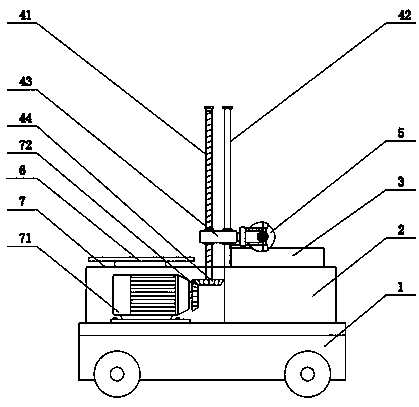
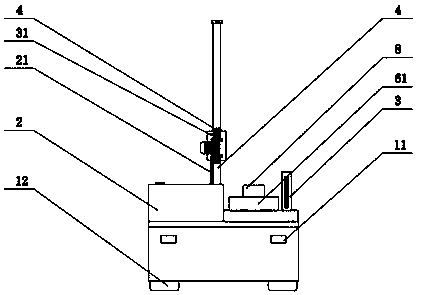
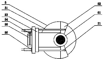
[0019] see Figure 1-Figure 5 As shown, the technical solution adopted in this specific embodiment is: it includes a mobile base 1, a cooling box 2, a vacuum cleaner 3, a lifting rod 4, a cutting device 5, a power generation assembly 6, a regulating device 7, and a control box 8; Box 2, vacuum cleaner 3, cutting device 4, lifting rod 5, power generation assembly 6, adjustment device 7, and control box 8 are all arranged above the mobile base 1, the vacuum cleaner 3 is arranged on the rear side of the cooling box 2, and the adjustment device 7 is fixedly installed On the left side of the cooling box 2, the power generation assembly 6 is installed on the top of the adjusting device 7, the lifting rod 4 is arranged above the adjusting device 7 and the cooling box 2, and the control box 8 is installed in the middle of the top of the mobile base 1. The cooling The box 2 is provided with a cooling pipe 21, the vacuum cleaner 3 is provided with a suction pipe 31, and the cutting devi...


PUM


Abstract

The invention discloses a cutting device for a building, and relates to the technical field of buildings. The cutting device for the building comprises a movable base, a cooling box, a dust collector,a lifting rod, a cutting device body, a power generation assembly, an adjusting device and a control box; the dust collector is arranged on the back side of the cooling box, the adjusting device is fixedly installed on the left side of the cooling box, the power generation assembly is installed on the top of the adjusting device, the lifting rod is arranged over the adjusting device and the cooling box, the control box is installed in the middle of the top of the movable base, the cooling box is provided with a cooling pipe, and the dust collector is provided with a dust collection pipe; andthe cutting device body comprises a motor, a cutting assembly, a rotating mechanism, a limiting mechanism, a telescopic rod and a telescopic device. According to the cutting device for the building, awall surface can be cut through rotation of a cutting wheel, the cutting wheel can achieve multi-position cutting, the problem of manual cutting is solved, and then the effects of reducing the laborintensity, improving the cutting efficiency and relieving arm aching are achieved.

Description

technical field [0001] The invention relates to the technical field of construction, in particular to a cutting device for construction. Background technique [0002] At present, the wall is hollowed out, and most of the interruptions are made by hammering with a sledgehammer. When encountering a hard wall, use a chainsaw to cut it. The more advanced wall cutting machine is relatively bulky and the application field is mostly the cutting of large buildings. It is not suitable for general home decoration. Ordinary sledgehammer will cause great damage to the wall, and cannot accurately cut the cutting part, and consumes a lot of manpower. Cutting with a chainsaw is more convenient, but the operator needs to hold it steadily when cutting the knife, otherwise there will be deviation, and it is very difficult to perform arc cutting. For the current relatively advanced wall cutting machines, most of them are used to cut hard walls, which are difficult to apply during decoration,...

Claims


Application Information

Patent Timeline
Patent Type & Authority Applications(China)
IPC IPC(8): B28D1/24B28D7/00B28D7/02
CPCB28D1/24B28D7/00B28D7/02
Inventor 高群张家颖樊群
Owner JINLING INST OF TECH
Why Eureka
Eureka Blog
Learn More