
A medicine box automatic folding mechanism

An automatic and medicine box technology, applied in the direction of container manufacturing machinery, box making operations, paper/cardboard containers, etc., can solve the problems of complex structure and high cost

Active Publication Date: 2020-07-07
SICHUAN HUILI IND
View PDF10 Cites 0 Cited by
  • Summary
  • Abstract
  • Description
  • Claims
  • Application Information

AI Technical Summary

Problems solved by technology

[0003] The purpose of the present invention is to provide an automatic hemming mechanism for medicine boxes to solve the problem that the cardboard hemming mechanism in the prior art needs to simultaneously control the tension on both sides of the punch very precisely, resulting in complex structure and high cost. Realize the purpose of simplifying the structure, reducing the cost of the box gluer, and forming the bent edge efficiently at the same time

Method used


Image

  • A medicine box automatic folding mechanism
  • A medicine box automatic folding mechanism
  • A medicine box automatic folding mechanism

Examples


Embodiment 1

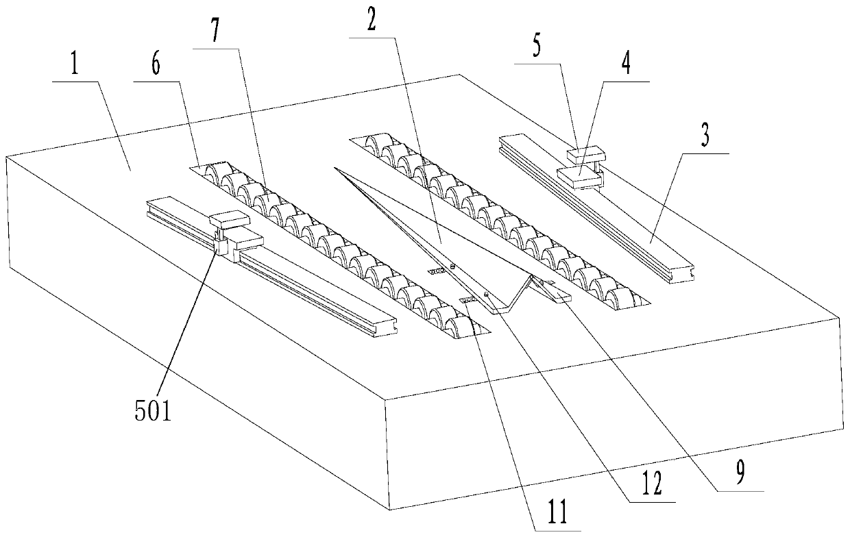
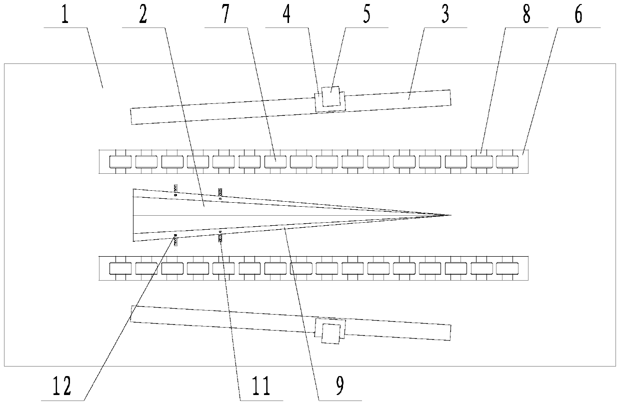
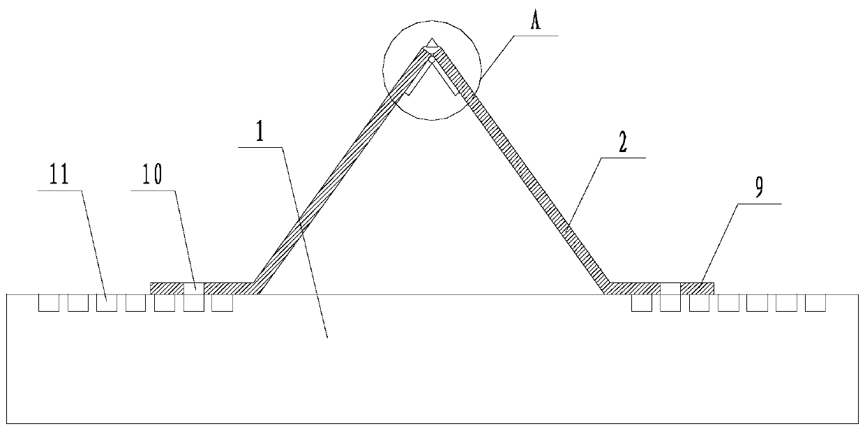
[0033] Such as Figure 1 to Figure 3 The shown automatic hemming mechanism for a medicine box comprises a table body 1, two hemming plates 2 are arranged on the table body 1, the top edges of the two hemming plates 2 are hinged to each other, and the two hemming plates 2 are connected to the The upper surface of the platform body 1 together forms a triangular pyramid structure, and the bottom end of the flanged plate 2 is fixedly connected with the mounting wing 9 that is movably placed on the platform body 1, and the threaded through hole 10 is set on the mounting wing 9, and the The bottom surface of the triangular pyramid structure is perpendicular to the platform body 1 upper surface, and the bottom surface of the triangular pyramid structure is an isosceles triangle with the apex facing up. The opposite sides of the triangular pyramid structure are all provided with guide mechanisms fixed on the platform body 1, and the guide mechanism is fixed on the platform body 1. The...

Embodiment 2

[0036] Such as Figure 1 to Figure 6 As shown, on the basis of Embodiment 1, the flanged plate 2 and the corresponding mounting wing 9 are integrally formed. The tops of the two flanging plates 2 are hinged by hinges 15 arranged on the bottom surfaces of the flanging plates 2, and elastic members 13 are bonded between the tops of the two flanging plates 2, and the bottoms are inserted into the elastic members 13. A hard pointed cone 14, the pointed end of the hard pointed cone 14 faces upward. The top surface of the slide block 4 is parallel to the upper surface of the table body 1, and the side of the slide block 4 away from the direction where the triangular pyramid structure is located is fixedly connected to the linear drive device 501 with the driving end facing upward, and the drive end of the linear drive device 501 is fixedly connected Clamping plate 502, the clamping plate 502 is located above the slider 4, the bottom surface of the clamping plate 502 is parallel to ...

Embodiment 3

[0038] Such as Figure 7 As shown, the linear guide rail 3 is fixedly connected with a mounting wing 9 far away from itself. Each linear guide rail 3 is fixedly connected with the fixed mounting wing 9 by two connecting rod assemblies 16, and the connecting rod assemblies 16 are located inside the platform body 1, and the platform body 1 is hollow, and the connecting rod assemblies 16 can be mounted on the platform body 1 move within. In this embodiment, a notch 17 for the connecting rod assembly 16 to pass through and move is provided on the upper surface of the table body 1 , and the length and width of the notch 17 can be adaptively set according to the lateral adjustment range of the mounting wing 9 .


PUM


Abstract

The invention discloses an automatic edge-folding mechanism for a medicine box. Two edge-folding boards are arranged on a table body; top sides of the two edge-folding boards are hinged with each other; the two edge-folding boards and the upper surface of the table body co-define a triangular pyramid structure; the bottom ends of the edge-folding boards are fixedly connected with a mounting wing which is movably placed on the table body; a threaded through hole is formed in the mounting wing; the automatic edge-folding mechanism is further equipped with a guide mechanism fixedly arranged on the table body; threaded blind holes which are uniformly distributed along a straight line are further formed in the table body; and a distributing direction of the threaded blind holes is perpendicularto a vertical line from the top point of the triangular pyramid structure to the bottom surface of the triangular pyramid structure. The automatic edge-folding mechanism solves the problems that thestructure is complex and the cost is extremely high as very precise control needs to simultaneously perform on tension at the two sides of a punch by a paperboard edge-folding mechanism in the prior art, and realizes the purposes of simplifying the structure, reducing the cost of a box sticking machine and efficiently forming bent sides.

Description

technical field [0001] The invention relates to the field of medicine packaging, in particular to an automatic edge folding mechanism for a medicine box. Background technique [0002] The box gluer is a special device for bonding various packaging boxes. Its working principle is to surround the original flat packaging box raw materials into the required shape, and then automatically apply glue for bonding. Therefore, it needs Bending the box raw material. In the prior art, there are mainly two types of edge folding methods for box gluers: stamping forming and edge folding wheel forming. Among them, the forming method of the hemming wheel is generally used for the hemming of plastic packaging and barrel-shaped packaging boxes, because the hemming wheel set can only form a curved section with a curvature, and cannot be used for the production of square packaging cartons. Therefore, stamping is the most commonly used process for carton processing. It uses the impact of a shar...

Claims


Application Information

Patent Timeline
Patent Type & Authority Patents(China)
IPC IPC(8): B31B50/26B31B50/74
CPCB31B50/26B31B50/74
Inventor 张辉柏金枝
Owner SICHUAN HUILI IND
Learn More