Ventilation fault prompt method, device and facility and storage medium

A technology for equipment and faults, which is applied in the field of equipment ventilation, can solve problems such as timely notification of non-ventilated faults, faults, poor heat dissipation of equipment, etc., and achieve the effect of ensuring long-term normal operation and avoiding faults

Inactive Publication Date: 2019-04-02
ZHENGZHOU YUNHAI INFORMATION TECH CO LTD
View PDF9 Cites 4 Cited by
  • Summary
  • Abstract
  • Description
  • Claims
  • Application Information

AI Technical Summary

Problems solved by technology

[0004] The purpose of the present invention is to provide a ventilation failure prompt method, device, equipment and computer-readable storage medium to solve the problem in the prior art that the ventilation failure is not prompted in time, resulting in failure of the equipment due to poor heat dissipation

Method used


Image

  • Ventilation fault prompt method, device and facility and storage medium
  • Ventilation fault prompt method, device and facility and storage medium
  • Ventilation fault prompt method, device and facility and storage medium

Examples


Embodiment Construction

[0040] In order to enable those skilled in the art to better understand the solution of the present invention, the present invention will be further described in detail below in conjunction with the accompanying drawings and specific embodiments. Apparently, the described embodiments are only some of the embodiments of the present invention, but not all of them. Based on the embodiments of the present invention, all other embodiments obtained by persons of ordinary skill in the art without making creative efforts belong to the protection scope of the present invention.

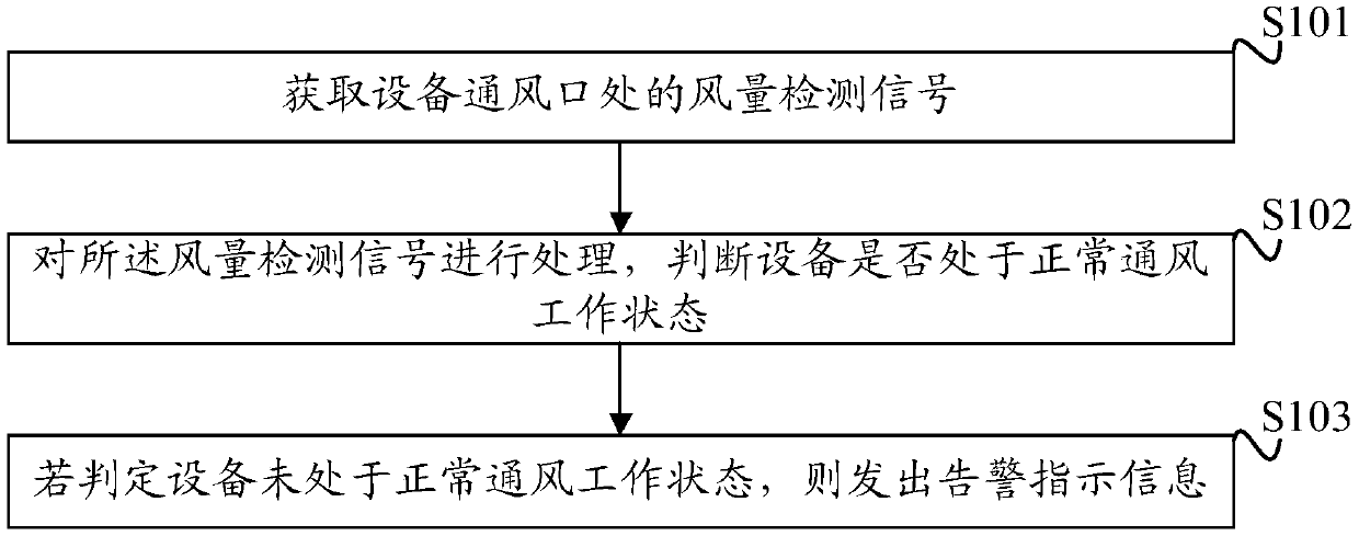
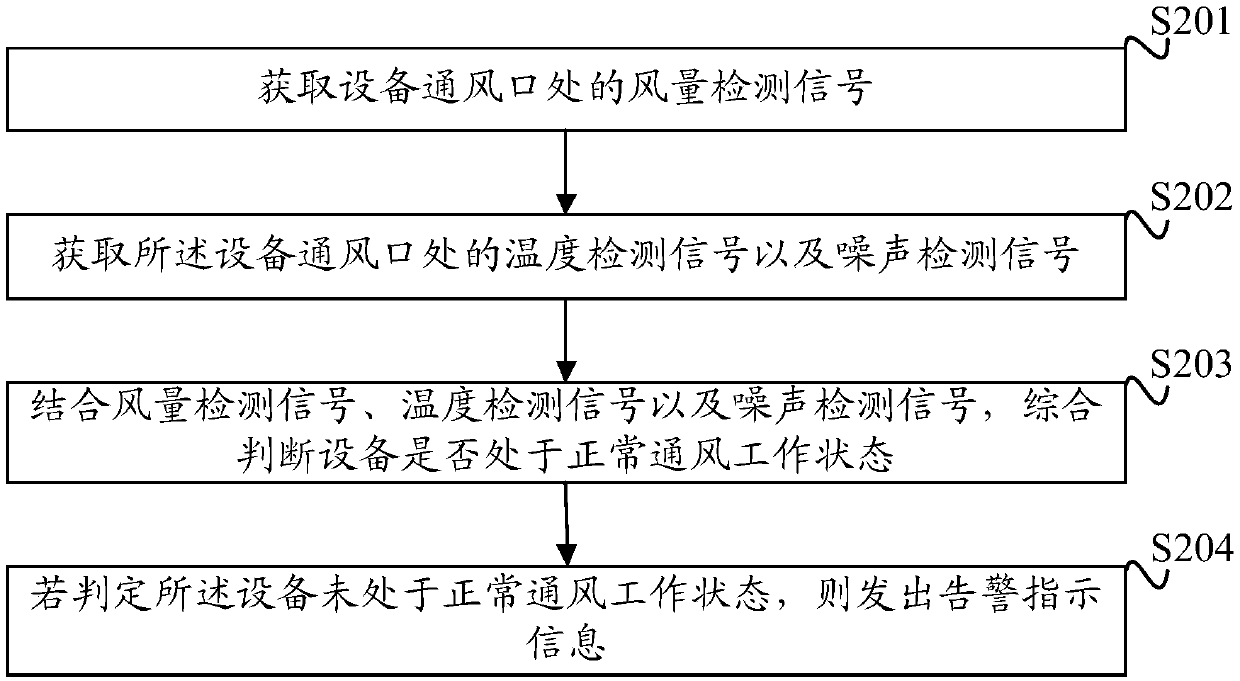
[0041] A flow chart of a specific implementation of the ventilation failure prompt method provided by the present invention is as follows: figure 1 As shown, this method can be applied to cabinets, and of course it can also be applied to other equipment that filters out fluid impurities through filters, such as the fault detection of air inlet filters of air conditioners, etc. The process specifically includes...


PUM


Abstract

The invention discloses a ventilation fault prompt method. Air volume detection signals at the equipment ventilation port position are obtained; the air volume detection signals are detected, and whether equipment is in the normal ventilation work state or not is judged; and if it is judged that the equipment is not in the normal ventilation work state, alarming prompt information is sent. A convenient ventilation fault prompt scheme is provided, no requirements exist for the usage habits and the equipment cabinet maintaining awareness of usage and maintenance personnel, prompt can be made forthe equipment cabinet ventilation fault in time, the situation of faults due to poor heat dissipation of the whole machine is avoided, and long-term normal running of the whole machine is guaranteed.In addition, the invention further provides a ventilation fault prompt device and facility with above technical effects and a computer readable storage medium.

Description

technical field [0001] The present invention relates to the technical field of equipment ventilation, in particular to a ventilation failure prompting method, device, equipment and computer-readable storage medium. Background technique [0002] At present, most of the cabinet equipment adopts air-cooling cooling measures, allowing the air with a lower temperature to enter from the air inlet, pass through the high-temperature area to be cooled, and transfer the heat to the air with a lower temperature after heat transfer occurs, and then the temperature rises. The air is discharged from the air outlet to complete the purpose of cooling the high temperature area to be cooled. [0003] In the air-cooling measures, it is ideal for the high-temperature area to transfer heat to the low-temperature air with high efficiency, but if the heat sink in the high-temperature area, such as the heat sink with fins to increase the heat exchange area, is covered with dust or other heat-insula...

Claims


Application Information

Patent Timeline
Patent Type & Authority Applications(China)
IPC IPC(8): F04D27/00F04D25/08F04D29/70H05K7/20
CPCF04D25/08F04D27/001F04D27/008F04D29/703H05K7/20554
Inventor 王麒
Owner ZHENGZHOU YUNHAI INFORMATION TECH CO LTD
Why Eureka
Try Eureka