Inflatable connector

A technology for inflatable joints and inflatable channels, applied in the direction of mechanical equipment, couplings, etc., can solve the problems of inconvenient operation, large resistance, and many components of the inflatable joint 1, and achieve the advantages of improved convenience, fewer components, and labor-saving operation Effect

Active Publication Date: 2020-05-15
BETO ENG & MARKETING
View PDF11 Cites 0 Cited by
  • Summary
  • Abstract
  • Description
  • Claims
  • Application Information

AI Technical Summary

Problems solved by technology

[0005] Although the aforementioned invention patent can achieve the expected creative purpose, the inflatable joint 1 not only has many components, but also needs to drive the cam lever 15 to pivot during the position conversion process. Due to the first contact surface 153 and the The distances from the second abutting surface 154 to the center of the bolt 14 are different. Therefore, when switching positions, the clamp ring 162 is actually pressed to become fatter and shorter. This operation method not only has a large resistance during operation, but also requires one hand. Support the base 13 and pull the cam lever 15 with one hand, so the aforementioned invention patents have large resistance during operation and are not very convenient to operate

Method used


Image

  • Inflatable connector
  • Inflatable connector
  • Inflatable connector

Examples


Embodiment Construction

[0028] Before the present invention is described in detail, it should be noted that in the following description, similar components are denoted by the same numerals.

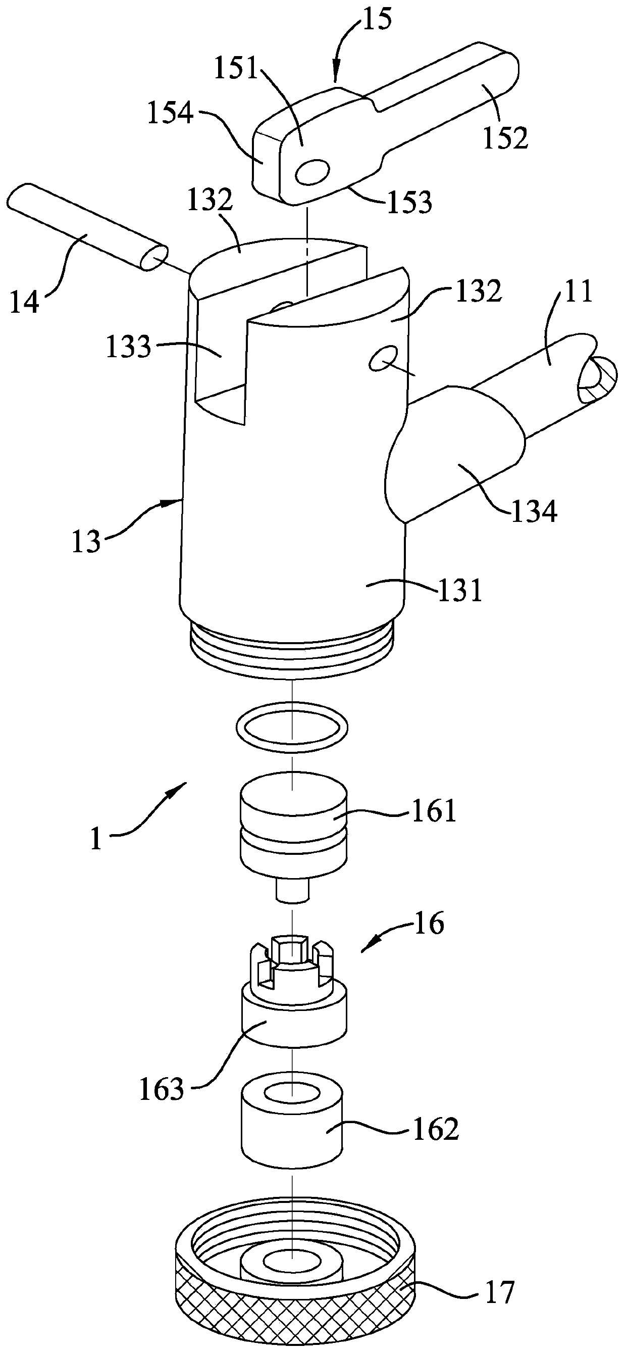
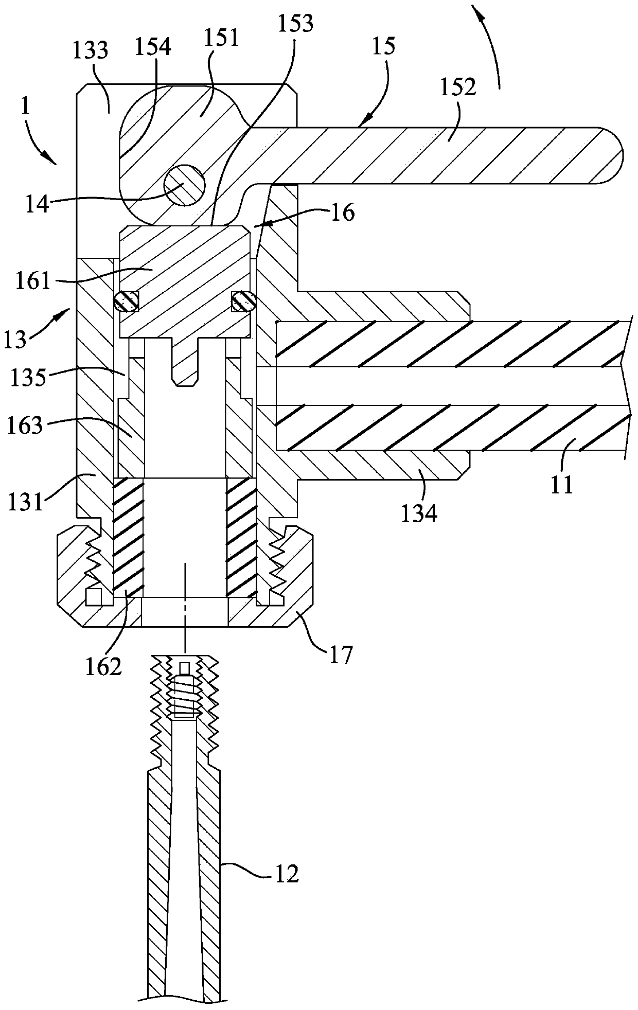
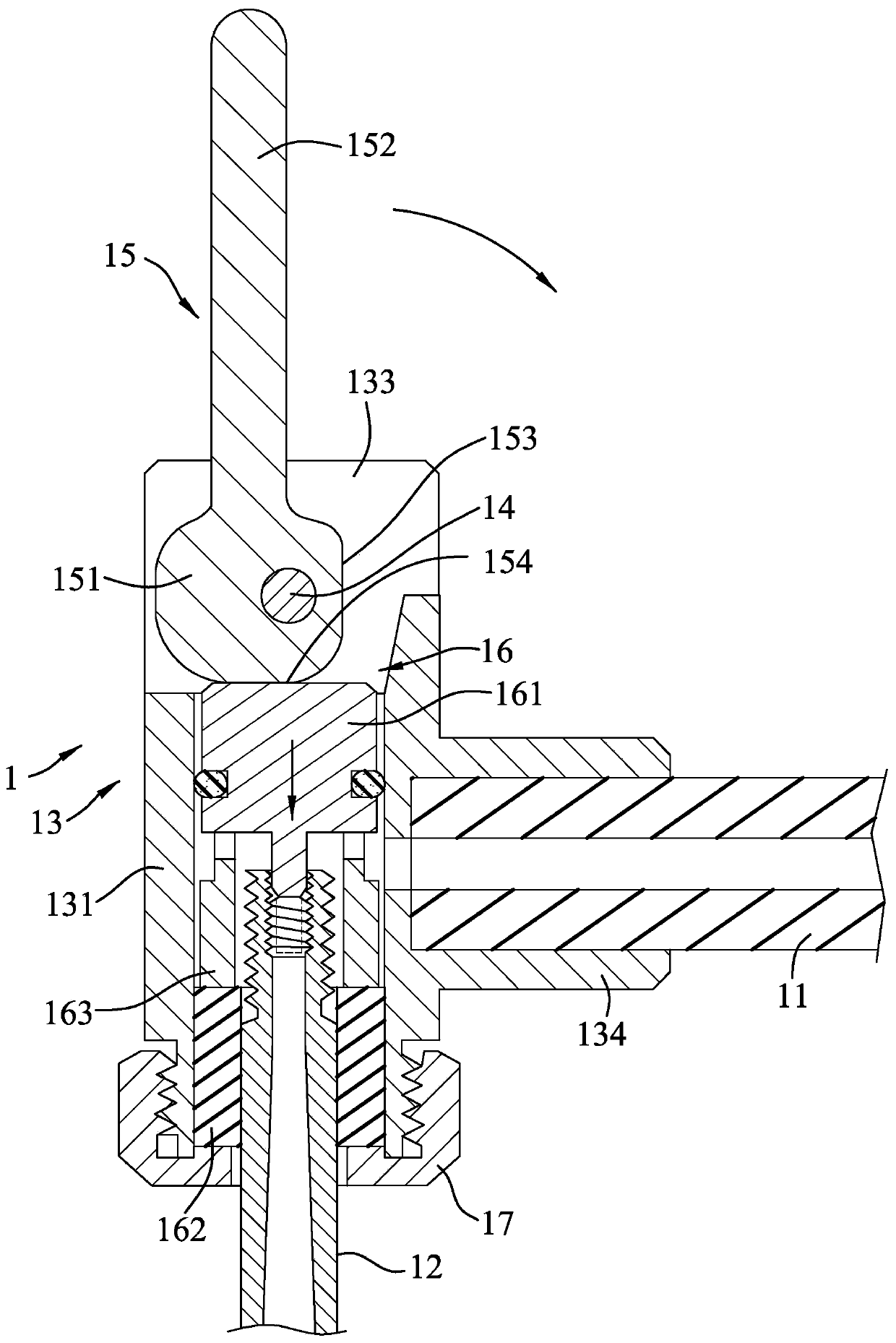
[0029] refer to Figure 4 , 5 , 6, a first embodiment of the inflation connector of the present invention is also used to connect a gas source 20 and a valve 21, the form of the gas source 20 is not particularly limited, it can be an electric or manual inflator or an inflator equipment, Figure 4 Only one pipe body used to deliver gas is shown, and the form of the valve 21 is not particularly limited. This embodiment shows a French valve (presta valve). Due to the improvement of the present invention and the structure of the valve 21 Irrelevant, no more details. The inflatable joint includes: an inflatable housing 3 for overlapping the gas source 20, a restraint 4 installed inside the inflatable housing 3, and a clamp that can drive the restraint 4 in a relaxed position. A control mechanism 5 for switching ...


PUM


Abstract

The invention discloses an inflating connector. The inflating connector is connected with an air source and an inflating valve, and comprises an inflatable shell, a binding piece and a control mechanism, wherein the inflatable shell is provided with a vent passage and a pressing wall, the binding piece is located in an assembling chamber of the inflating shell and is provided with a binding hole allowing the inflating valve to penetrate, and the control mechanism is provided with a control valve installed in the assembling chamber, an elastic piece used for pushing the control valve towards the pressing wall to jointly clamp and press the binding piece, and a control handle which is arranged on the inflatable shell in a pivoting manner and is in linkage with the control valve. According to the inflating connector, the structures cooperate with each other so that the binding piece can be reset through simple and labor-saving operation, then the inflating valve can be conveniently inserted, and meanwhile, when the external force is released, the binding piece can automatically clamp and fix the inflating valve.

Description

technical field [0001] The invention relates to a joint, in particular to an inflatable joint used to connect a gas source and a gas valve. Background technique [0002] refer to figure 1 , 2 , 3, is the invention patent of US5,762,095, which discloses an inflatable joint 1 for connecting a gas source 11 and a valve 12, the inflatable joint 1 includes a base 13, and the base 13 has a barrel shaped base 131, two flanges 132 protruding upward from the base 131 and spaced apart, a channel 133 interposed between the flanges 132, and a channel 133 protruding from the base 131 and supplying the gas The source 11 is installed with a connecting pipe portion 134 , and the base portion 131 has a chamber 135 in the axial direction and communicated with the channel 133 . The inflatable joint 1 also includes a cam bar 15 pivotably installed in the groove 133 of the base 13 through a latch 14, a clamping device 16, and a clamping device 16 mounted on The end cap 17 within the chamber ...

Claims


Application Information

Patent Timeline
Patent Type & Authority Patents(China)
IPC IPC(8): F16L37/46F16L37/08
CPCF16L37/08F16L37/46
Inventor 王罗平
Owner BETO ENG & MARKETING
Why Eureka
Try Eureka