Mixed excitation permanent magnet motor based on three-stage stator axial complementary structure

A hybrid excitation, permanent magnet motor technology, applied in the magnetic circuit shape/style/structure, electrical components, electromechanical devices, etc., can solve the problems of interference harmonic waste, magnetic circuit asymmetry, interference harmonic utilization, etc. Torque Density and Power Density, Harmonic Distortion Reduction, Effect of Harmonic Distortion Reduction

Active Publication Date: 2019-04-02
SOUTHEAST UNIV
View PDF3 Cites 10 Cited by
  • Summary
  • Abstract
  • Description
  • Claims
  • Application Information

AI Technical Summary

Problems solved by technology

As a result, the amplitudes of the opposite potentials are not equal, which will greatly affect the electromagnetic parameter characteristics of the motor
[0006] In order to solve the asymmetric topological magnetic circuit of "heteropolar" motors, some studies have adopted the method of multi-winding, but because the number of stator teeth is not equal to the number of rotor pole pairs, multi-winding still cannot completely solve the problem of magnetic circuit asymmetry. , at the same time, if the electric excitation winding is added, the asymmetry of the magnetic cir

Method used


Image

  • Mixed excitation permanent magnet motor based on three-stage stator axial complementary structure
  • Mixed excitation permanent magnet motor based on three-stage stator axial complementary structure
  • Mixed excitation permanent magnet motor based on three-stage stator axial complementary structure

Examples


Embodiment 1

[0074] Embodiment 1: If the outer stator of the present invention is not segmented, it is simply referred to as the original "heteropolarity" dual stator topology.

Embodiment 2

[0075] Embodiment 2: If the outer stator of the present invention is not segmented, and the outer stator segments all adopt the form of "multi-winding", it is referred to as the improved "multi-winding" dual-stator topology.

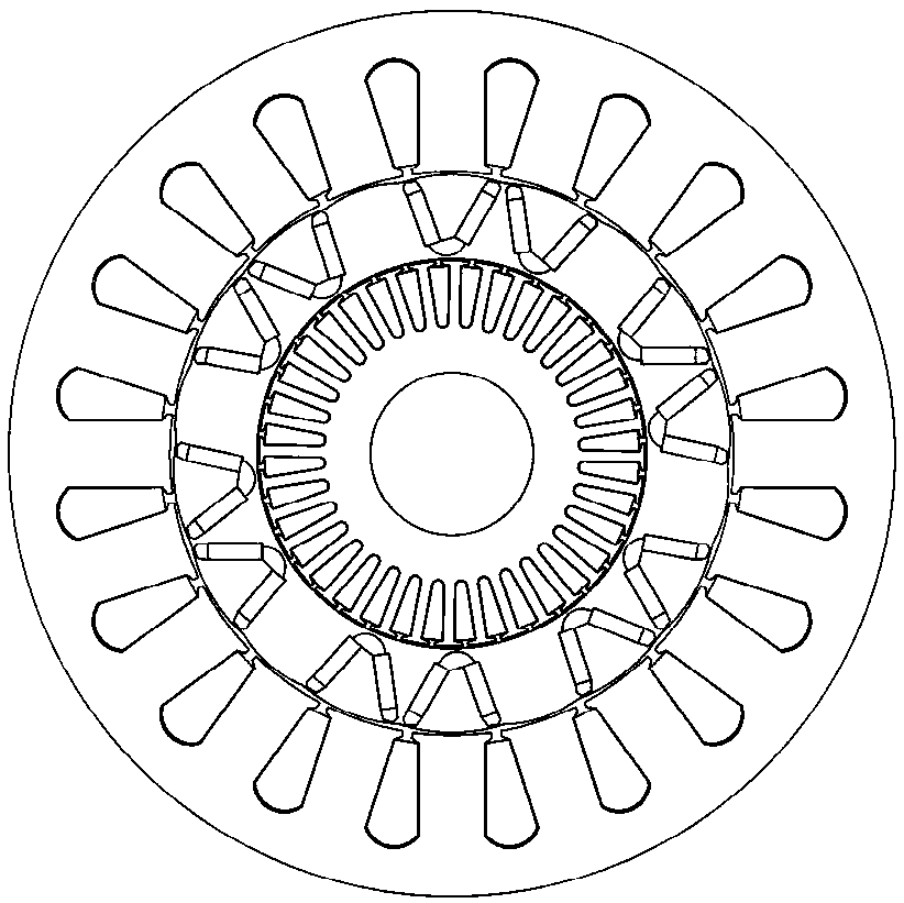
[0076] The above-mentioned original "heteropolarity" dual-stator topology and the improved "multi-winding" dual-stator topology are basically the same as the topological structure diagram of a single stator segment in the present invention, as shown in figure 2 As shown, a cross-sectional topology of a single stator segment of the present invention is shown.

[0077] For the original "heteropolarity" dual-stator topology and the improved "multi-winding" dual-stator topology, the magnetic circuit asymmetry will appear to varying degrees, and this magnetic circuit asymmetry will directly lead to empty phases in each phase. The magnitude of the load back EMF is different, such as Figure 8-1 and Figure 8-2 shown.

[0078] The following theory explains ...


PUM


Abstract

The invention discloses a mixed excitation permanent magnet motor based on a three-stage stator axial complementary structure. An outer stator of the mixed excitation permanent magnet motor comprisesthree outer stator stages arranged along the axial direction in an equally-spaced manner, the difference of the initial angles of every two adjacent outer stages is a mechanical angle alpha, and alphais equal to 360 degrees/p, wherein p is the number of pole-pairs of the motor, p is equal to 3i, and i is a positive integer; an armature winding is wound on the outer stator teeth of each outer stator stage respectively, and each armature winding is a fractional-slot concentrated winding respectively; the rotor is an internally installed V-shaped rotor with heteropolarly alternated poles, the rotor is provided with 2p/3 permanent magnet pole pairs and p/3 iron core pole pairs; an exciting winding is wound on the inner stator teeth of the inner stator, the number of pole-pairs of the excitingwinding is p/3, and each exciting winding is an integer slot distributed winding respectively. The flux density of an outer air gap can be changed by taking the iron core pole of the rotor as a channel in a rotating magnetic field generated by the inner stator, and the problem that the counter potential amplitudes are unequal existing in the heteropolarly alternated poles is solved. Moreover, themanufacturing cost and demagnetization risk are reduced while the reliability is improved.

Description

technical field [0001] The invention relates to the field of motor structure design, in particular to a hybrid excitation permanent magnet motor based on a three-stage stator axial complementary structure. Background technique [0002] With the rapid development of permanent magnet motor technology, various new permanent magnet motors have been widely used. According to statistics, the global consumption of rare earth permanent magnet materials has reached 20% of the total consumption of magnetic materials in 2015. my country is a major producer of rare earth permanent magnet materials, and the consumption of rare earths in 2015 was as high as 40%, reaching 80,000 tons. Since 2005, the global rare earth consumption has continued to grow at a rate of nearly 3.36% per year, and China occupies an absolute dominant position in it. At present, China's rare earths account for 85% of the global rare earth supply, which will greatly consume the existing rare earth permanent magnet...

Claims


Application Information

Patent Timeline
IPC IPC(8): H02K16/04H02K1/14H02K1/27
CPCH02K1/14H02K1/27H02K16/04H02K2213/03
Inventor 樊英瞿广宇
Owner SOUTHEAST UNIV
Why Eureka
Try Eureka