A Prediction Method Based on Video Compression

A prediction method and video compression technology, applied in the direction of digital video signal modification, image communication, electrical components, etc., can solve problems such as the limited information of the prediction method and the quality of video compression, so as to reduce the theoretical limit entropy and improve quality effect

Active Publication Date: 2020-12-15
广东弘视数字传媒有限公司
View PDF7 Cites 0 Cited by
  • Summary
  • Abstract
  • Description
  • Claims
  • Application Information

AI Technical Summary

Problems solved by technology

[0004] However, when the texture of the image to be compressed in the video is relatively complex, the existing prediction methods are limited by limited information, and cannot make full use of the correlation between textures to effectively predict the image to be compressed, thus affecting the quality of video compression

Method used


Image

  • A Prediction Method Based on Video Compression
  • A Prediction Method Based on Video Compression
  • A Prediction Method Based on Video Compression

Examples


Embodiment 1

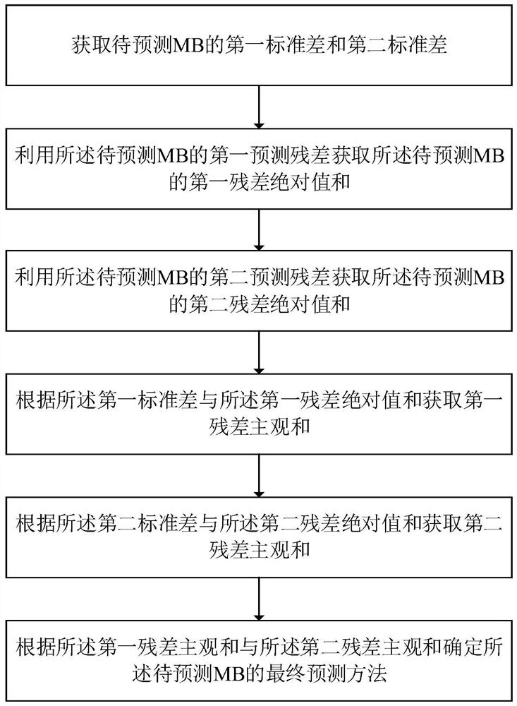
[0066] See figure 1 , figure 1 It is a schematic flowchart of a prediction method based on video compression provided by an embodiment of the present invention. The forecasting method includes the following steps:

[0067] Step 1. Obtain the first standard deviation and the second standard deviation of the MB to be predicted;

[0068] Step 2, using the first prediction residual of the MB to be predicted to obtain the absolute value sum of the first residual of the MB to be predicted;

[0069] Step 3, using the second prediction residual of the MB to be predicted to obtain the second absolute value sum of the MB to be predicted;

[0070] Step 4. Acquiring the subjective sum of the first residual error according to the first standard deviation and the absolute value sum of the first residual error;

[0071] Step 5. Acquiring a second residual subjective sum according to the second standard deviation and the second residual absolute value sum;

[0072] Step 6. Determine a fi...

Embodiment 2

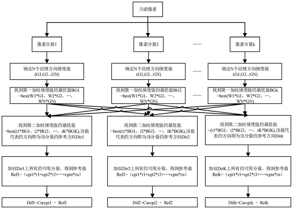
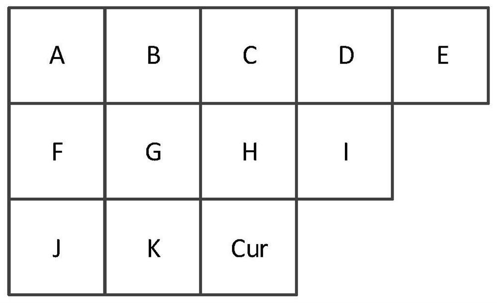
[0090] See figure 2 with image 3 , figure 2 It is a schematic diagram of the algorithm principle of a pixel-level multi-component reference adaptive direction prediction method provided by the embodiment of the present invention, image 3 A schematic diagram of a reference pixel position provided by an embodiment of the present invention. This embodiment describes in detail the pixel-level multi-component reference adaptive direction prediction method proposed by the present invention on the basis of the above embodiments. The prediction method includes the following steps:

[0091] S1. Define the size of the MB to be predicted as m*n, where m and n are natural numbers greater than zero;

[0092] S2. Define that the current pixel of the MB to be predicted has K pixel components, wherein K is a natural number greater than zero, and the K pixel components are respectively pixel component 1, pixel component 2...pixel component K;

[0093] S3. For each pixel component of th...

Embodiment 3

[0118] See Figure 4 with Figure 5 , Figure 4 A schematic diagram of gradient value calculation provided by the embodiment of the present invention; Figure 5 It is a schematic diagram of an algorithm principle of another pixel-level multi-component reference adaptive direction prediction method provided by an embodiment of the present invention. On the basis of the above-mentioned embodiments, this embodiment describes the pixel-level multi-component reference adaptive direction prediction method proposed by the present invention by way of example. In this embodiment, the pixel of the current pixel is divided into three components of Y, U, and V, and the specific steps are as follows:

[0119] S1. Define the size of the MB to be predicted as m*n, where m and n are natural numbers greater than zero;

[0120] S2. Define that the current pixel of the MB to be predicted has three pixel components, which are pixel component Y, pixel component U, and pixel component V;

[01...


PUM


Abstract

The invention relates to a prediction method based on video compression, which comprises the steps of obtaining first standard deviation and second standard deviation of an MB to be predicted; obtaining the first sum of absolute difference of the MB to be predicted by using first prediction residuals of the MB to be predicted; obtaining the second sum of absolute difference of the MB to be predicted by using second prediction residuals of the MB to be predicted; obtaining the first subjective difference according to the first standard deviation and the first sum of absolute difference; obtaining the second subjective difference according to the second standard deviation and the second sum of absolute difference; and determining a final prediction method for the MB to be predicted accordingto the first subjective difference and the second subjective difference. Various prediction methods are adopted for the same image to be compressed, and the image to be compressed adaptively selectsone prediction method for prediction according to the texture correlation, thereby enabling the image to be compressed to select a prediction method for prediction in a targeted manner, and greatly improving the quality of video compression.

Description

technical field [0001] The invention relates to the technical field of video compression, in particular to a prediction method based on video compression. Background technique [0002] Video processing technology is flourishing along with the transition of video from analog to digital. As people have more and more stringent requirements on the clarity, fluency, and real-time of video images, it has become a hot technology. At the same time, due to the current prosperity of surrounding industries such as Internet and display equipment, the development of video processing technology has also been promoted. Video processing technology can be subdivided into sub-disciplines such as image enhancement technology, video compression and decompression technology, and digital video broadcasting technology, which are applied to various industries such as communication, home and personal entertainment, security, medical care, and military affairs. Among them, video compression technol...

Claims


Application Information

Patent Timeline
Patent Type & Authority Patents(China)
IPC IPC(8): H04N19/103H04N19/176H04N19/182H04N19/96H04N19/50H04N19/184
CPCH04N19/103H04N19/176H04N19/182H04N19/184H04N19/50H04N19/96
Inventor 田林海李雯岳庆冬
Owner 广东弘视数字传媒有限公司
Why Eureka
Try Eureka