Device for controlling parallel link mechanism

A technology of linkage mechanism and control device, which is applied in the direction of controller, program control, electric controller, etc. with specific characteristics, can solve the problems of low responsiveness and low mechanical rigidity of the actuator, reduce adjustment man-hours, restrain The effect of vibration

Active Publication Date: 2019-04-02
MITSUBISHI ELECTRIC CORP
View PDF6 Cites 0 Cited by
  • Summary
  • Abstract
  • Description
  • Claims
  • Application Information

AI Technical Summary

Problems solved by technology

[0004] In response to the above knowledge, in the control device described in Patent Document 1, vibration is suppressed by changing the value of a parameter of the control system (hereinafter referred to as "control parameter") so that the mechanical rigidity becomes lower and the actuator The higher the feed rate, the less responsive the actuator becomes

Method used


Image

  • Device for controlling parallel link mechanism
  • Device for controlling parallel link mechanism
  • Device for controlling parallel link mechanism

Examples


Embodiment approach 1

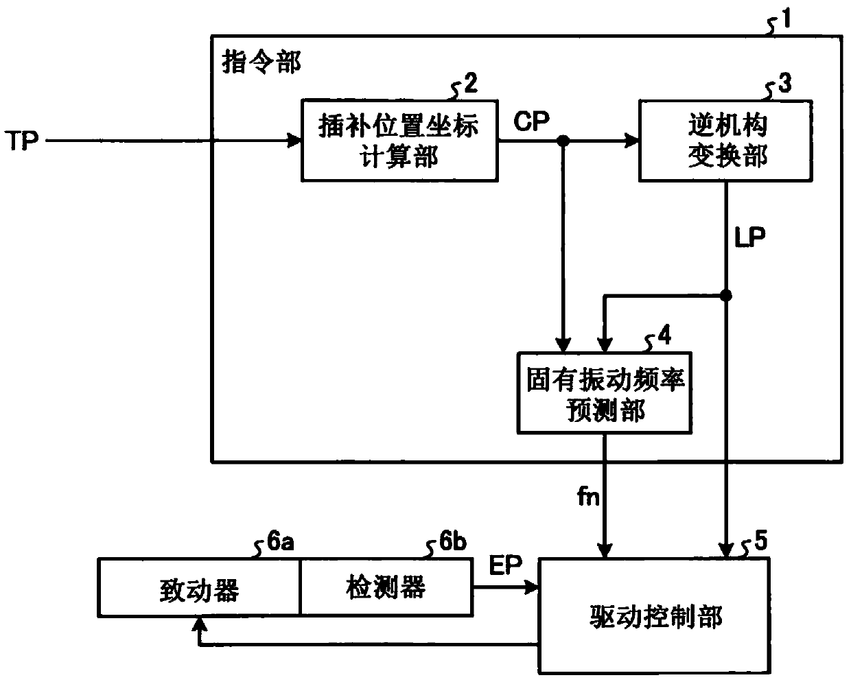
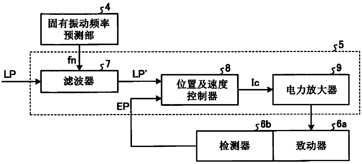
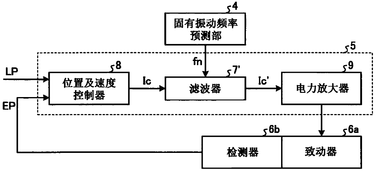
[0024] figure 1 It is a block diagram showing the functional configuration of the control device of the parallel link mechanism (hereinafter, abbreviated as "control device" as appropriate) according to the first embodiment. exist figure 1 Among them, the control device according to Embodiment 1 includes: a drive control unit 5 that controls the drive of the parallel link mechanism; and an instruction unit 1 that sends commands for controlling the actuator 6a to the drive control unit. 5 endowed.

[0025] like figure 1 As shown, the instruction unit 1 has an interpolation position coordinate calculation unit 2 and an inverse mechanism transformation unit 3 . The interpolation position coordinate calculation unit 2 calculates the interpolation position coordinate CP of the trajectory up to the target position of the end effector based on the target position TP of the end effector. The inverse mechanism conversion unit 3 calculates the target position command LP of the actua...

Embodiment approach 2

[0067] Next, a control device according to Embodiment 2 will be described. Figure 9 It is a block diagram showing the functional configuration of the control device according to the second embodiment. In Embodiment 2, in figure 1 In the configuration of the first embodiment shown, a spring constant estimation unit 100 is added to the command unit 1 , and an external measuring device 101 is added to the outside of the command unit 1 . The actual vibration frequency fn_real measured by the external measuring device 101 is input to the spring constant estimation unit 100 , and the estimated spring constant kest estimated by the spring constant estimation unit 100 is input to the natural frequency estimation unit 4 . Also, with respect to other structures, with figure 1 The structure of Embodiment 1 shown is the same or equivalent, and the same or equivalent structural parts are assigned the same reference numerals and redundant descriptions are omitted. In addition, the actua...

Embodiment approach 3

[0072] Next, a control device according to Embodiment 3 will be described. Figure 10 It is a block diagram showing the functional configuration of the control device according to the third embodiment. In Embodiment 3, in Figure 9 In the configuration of the second embodiment shown, a characteristic change detection unit 102 is added to the command unit 1 . The characteristic change detection unit 102 is configured to output an alarm signal to the outside based on the estimated spring constant kest estimated by the spring constant estimation unit 100 . Also, with respect to other structures, with Figure 9 The configurations of Embodiment 2 shown are the same or equivalent, and the same or equivalent configuration parts are assigned the same reference numerals and redundant descriptions are omitted.

[0073] Next, operations of main parts of the control device according to Embodiment 3 will be described. The characteristic change detection unit 102 monitors and stores the...


PUM


Abstract

A device for controlling a parallel link mechanism comprises an instruction unit (1) in which instructions for controlling an actuator (6a) and a drive control unit (5) that control driving of the parallel link mechanism are issued to the drive control unit (5). The instruction unit (1) is provided with a natural frequency estimation unit (4) that calculates, for each interpolation position of anend effector, an estimated value of the natural frequency, which changes in response to the position of the end effector. The calculations are made according to a dynamic model obtained by simulatinga mechanical system from the base of the parallel link mechanism to a link joining part using a translation spring and simulating a mechanical system from the link joining part to the end effector using a single rigid body. The drive control unit (5) is provided with a filter that, for each interpolation position, changes a frequency component that is suppressed in accordance with an estimated value sequence for each interpolation position of the end effector calculated by the natural frequency estimation unit (4).

Description

technical field [0001] The present invention relates to a control device for a parallel link mechanism in which a plurality of links are connected in parallel through joints. Background technique [0002] In the parallel link mechanism, a plurality of links are connected in parallel by joints between the base and the end effector. A part or all of the connecting rods are driven by the actuator to drive and control the end effector to a free position or to a free attitude. [0003] In Patent Document 1 below, there is a finding that when the end effector is in a state away from the origin position, vibration occurs during driving due to a reduction in the rigidity of the parallel link mechanism. [0004] In response to the above knowledge, in the control device described in Patent Document 1, vibration is suppressed by changing the value of a parameter of the control system (hereinafter referred to as "control parameter") so that the mechanical rigidity becomes lower and the...

Claims


Application Information

Patent Timeline
Patent Type & Authority Applications(China)
IPC IPC(8): B25J11/00G05B11/36
CPCB25J11/00G05B11/36G05B2219/41G05B2219/40G05B2219/39B25J9/1641B25J9/1623B25J9/1694B25J19/02G05B2219/41006
Inventor 岩濑正兴
Owner MITSUBISHI ELECTRIC CORP
Why Eureka
Try Eureka