Control device for parallel linkage mechanism
A link mechanism and control device technology, which is applied to controllers with specific characteristics, program control, electric controllers, etc., can solve the problems of low responsiveness and low mechanical rigidity of actuators, reduce adjustment man-hours, and suppress The effect of vibration
- Summary
- Abstract
- Description
- Claims
- Application Information
AI Technical Summary
Problems solved by technology
Method used
Image
Examples
Embodiment approach 1
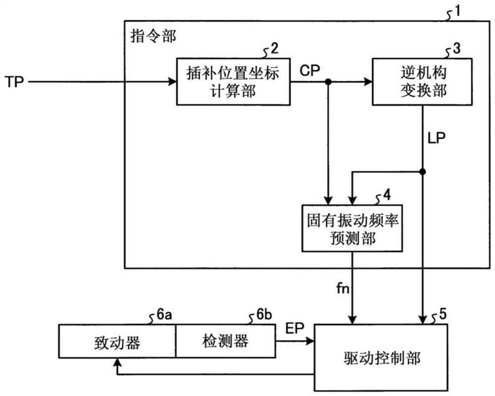
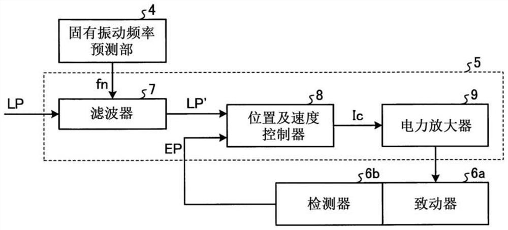
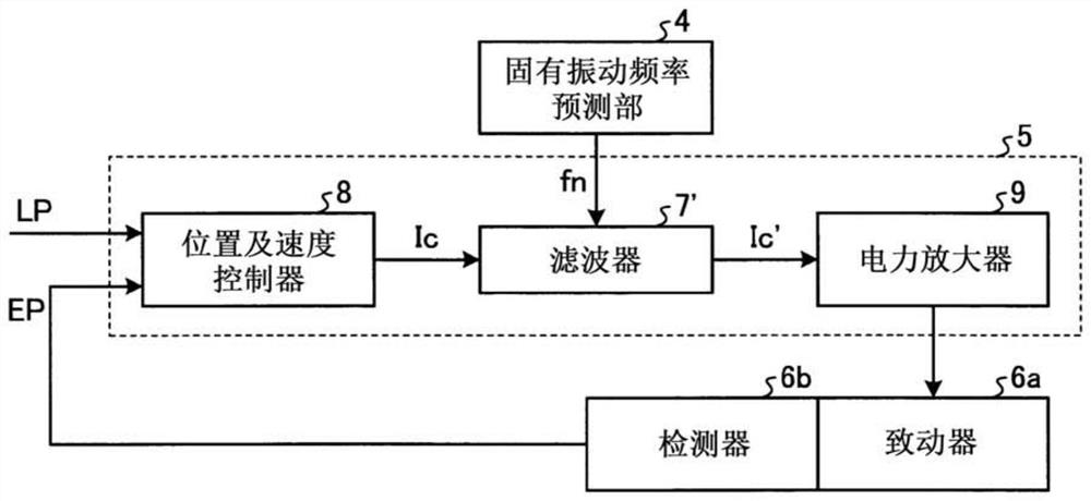
[0024] figure 1 It is a block diagram showing the functional configuration of the control device of the parallel link mechanism (hereinafter, abbreviated as "control device" as appropriate) according to the first embodiment. exist figure 1 Among them, the control device according to Embodiment 1 includes: a drive control unit 5 that controls the drive of the parallel link mechanism; and an instruction unit 1 that sends commands for controlling the actuator 6a to the drive control unit. 5 endowed.
[0025] like figure 1 As shown, the instruction unit 1 has an interpolation position coordinate calculation unit 2 and an inverse mechanism conversion unit 3 . The interpolation position coordinate calculation unit 2 calculates the interpolation position coordinate CP of the trajectory up to the target position of the end effector based on the target position TP of the end effector. The inverse mechanism conversion unit 3 calculates the target position command LP of the actuator ...
Embodiment approach 2
[0067] Next, a control device according to Embodiment 2 will be described. Figure 9 It is a block diagram showing the functional configuration of the control device according to the second embodiment. In Embodiment 2, in figure 1 In the configuration of the first embodiment shown, a spring constant estimation unit 100 is added to the command unit 1 , and an external measuring device 101 is added to the outside of the command unit 1 . The actual vibration frequency fn_real measured by the external measuring device 101 is input to the spring constant estimation unit 100 , and the estimated spring constant kest estimated by the spring constant estimation unit 100 is input to the natural frequency estimation unit 4 . Also, with respect to other structures, with figure 1 The structure of Embodiment 1 shown is the same or equivalent, and the same or equivalent structural parts are assigned the same reference numerals and redundant descriptions are omitted. In addition, the actua...
Embodiment approach 3
[0072] Next, a control device according to Embodiment 3 will be described. Figure 10 It is a block diagram showing the functional configuration of the control device according to the third embodiment. In Embodiment 3, in Figure 9 In the configuration of the second embodiment shown, a characteristic change detection unit 102 is added to the command unit 1 . The characteristic change detection unit 102 is configured to output an alarm signal to the outside based on the estimated spring constant kest estimated by the spring constant estimation unit 100 . Also, with respect to other structures, with Figure 9 The configurations of Embodiment 2 shown are the same or equivalent, and the same or equivalent configuration parts are assigned the same reference numerals and redundant descriptions are omitted.
[0073] Next, operations of main parts of the control device according to Embodiment 3 will be described. The characteristic change detection unit 102 monitors and stores the...
PUM
 Abstract
Description
Claims
Application Information
 - R&D
- Intellectual Property
- Life Sciences
- Materials
- Tech Scout
- Unparalleled Data Quality
- Higher Quality Content
- 60% Fewer Hallucinations
Browse by: Latest US Patents, China's latest patents, Technical Efficacy Thesaurus, Application Domain, Technology Topic, Popular Technical Reports.
© 2025 PatSnap. All rights reserved.Legal|Privacy policy|Modern Slavery Act Transparency Statement|Sitemap|About US| Contact US: help@patsnap.com


