
Seedling tray laying device with one side upper tray and its laying method

A laying device and plate laying technology, which is applied to botany equipment and methods, filling of flower pots, and counting of items shipped through a conveying device, etc., can solve uneven plate placement, large labor demand, and high labor intensity And other problems, to achieve the effect of improving neatness, controlling the number of entries, and accurately entering the number

Active Publication Date: 2020-12-22
浙江德菲洛智能机械制造有限公司
View PDF4 Cites 0 Cited by
  • Summary
  • Abstract
  • Description
  • Claims
  • Application Information

AI Technical Summary

Problems solved by technology

After the seedlings emerge neatly in the darkroom, they will be transported manually to the greenhouse or seedling field for secondary seedling cultivation. The process of manual transport is labor-intensive and requires a large labor force. A mechanical device is urgently needed to replace the manual work of laying the trays.
Although the existing plate-setting equipment can complete the operation of seedling raising and plate-setting, because of problems such as the stagnation of the seedling plate on the inclined-plane slideway of the spreading plate, the plate-setting is uneven, and it is also unable to adapt to the simultaneous laying of multi-ridge fields. The demand for trays leads to low efficiency of laying trays, which cannot meet the comprehensive operation requirements of modern agriculture with high efficiency and high quality.

Method used


Image

  • Seedling tray laying device with one side upper tray and its laying method
  • Seedling tray laying device with one side upper tray and its laying method
  • Seedling tray laying device with one side upper tray and its laying method

Examples


Embodiment Construction

[0038] The present invention will be further described below in conjunction with accompanying drawing.

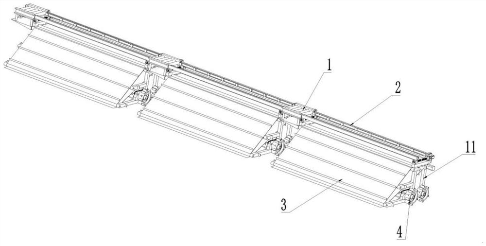
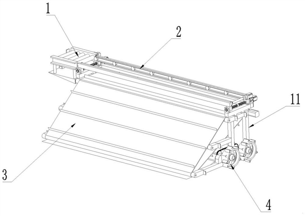
[0039] Such as figure 1 with 2 As shown, a seedling tray laying device with one side upper tray includes n sub-layout modules, n=3. The sub-layout module includes a roller conveying module 1 and a spreader car. The width of the paving vehicle is equal to the width of a ridge of field to be paved. The length of the roller conveyor module 1 is equal to the distance between two adjacent ridges (that is, the width of the groove or road between the ridges).

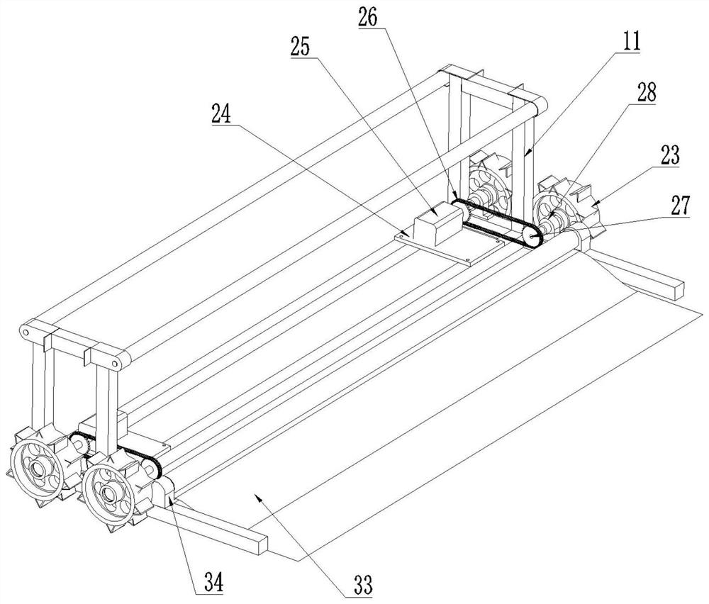
[0040] The plate-laying vehicle includes a horizontal plate-transfer mechanism 2, a vertical plate-laying mechanism 3, a traveling mechanism 4 and a support frame 11. The roller conveyor tray module 1 is fixed on one end of the support frame 11 by the support plate 10, and is used for transporting the seedling raising tray to the tray car. The vertical plate laying mechanism 3 is installed on the support frame 11, and ...


PUM


Abstract

The invention discloses a seedling tray laying device for a single-side tray and a tray laying method thereof. Although the existing swing disc equipment can finish the swing disc operation of seedling raising, the problems that the seedling disc descends and stagnates on the slope slide of the spreading disc, and the like are not solved. The present device includes a sub-deck module, which comprises a disk laying vehicle, wherein the disk laying vehicle comprises a transverse disk conveying mechanism, a longitudinal disk laying mechanism, a travel mechanism and a supporting frame. The travelmechanism includes a single-side travel assembly. The one-sided travel assembly includes a wheel and a travel drive. The transverse disk conveying mechanism comprises a bidirectional threaded screw rod, a first screw rod motor, a second screw rod motor, a single-side disk conveying assembly, a transverse conveyor belt motor and a telescopic transmission shaft. The single-side disk conveying assembly comprises a transmission belt mounting plate, a horizontal transmission belt and a transverse power belt wheel. The longitudinal disk laying mechanism comprises a longitudinal disk conveying motor,a partition plate conveyor belt, a first roller, and a second roller and a fourth roller. The device skillfully completes the switching between the transverse disk conveying and the longitudinal diskconveying by changing the distance between the horizontal conveying belts.

Description

technical field [0001] The invention belongs to the technical field, and in particular relates to a device for laying seedling trays with one side upper tray and a method for laying trays. Background technique [0002] With the development of mechanization of agricultural production in my country, automatic production lines are mostly used in rice seedling raising to improve the quality of seedlings. After passing through the automatic seedling raising line, the soil covering, sowing and soil covering are completed in the seedling raising tray. Then put it in a dark room to keep warm and moisturize intensively, and the seedlings will emerge. After the seedlings are in order in the darkroom, they are manually transported to the seedling hardening shed or the seedling field for secondary seedling cultivation. The process of manual transport is labor-intensive and requires a large labor force. A mechanical device is urgently needed to replace the manual work of laying the tray...

Claims


Application Information

Patent Timeline
Patent Type & Authority Patents(China)
IPC IPC(8): A01G9/029A01G9/08G06M7/00
CPCA01G9/088A01G9/029A01G9/0295G06M7/00
Inventor 武传宇黄建勋
Owner 浙江德菲洛智能机械制造有限公司
Learn More