
Two-wheeled adjustable cleaning vehicle

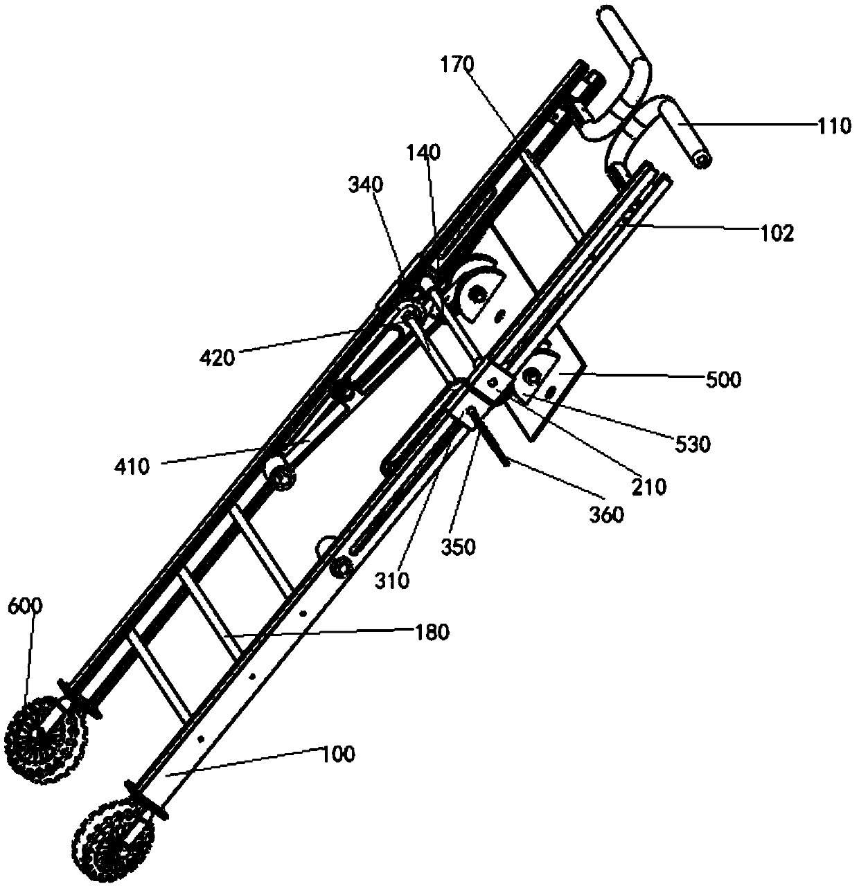
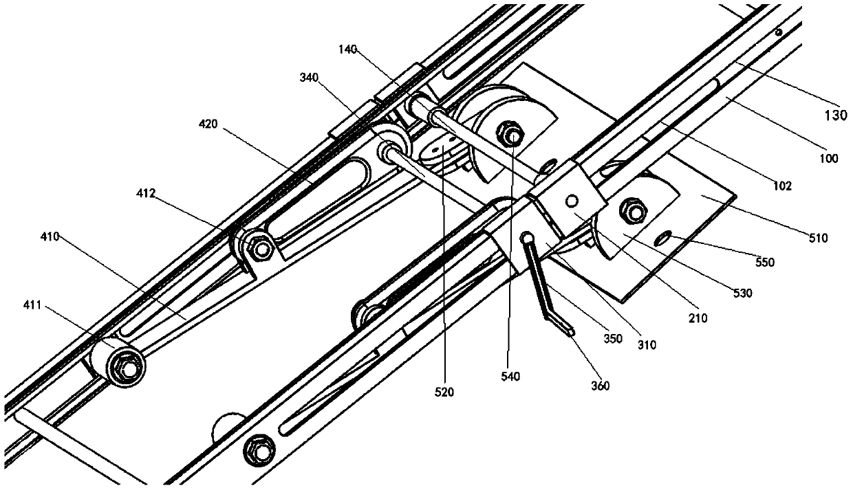
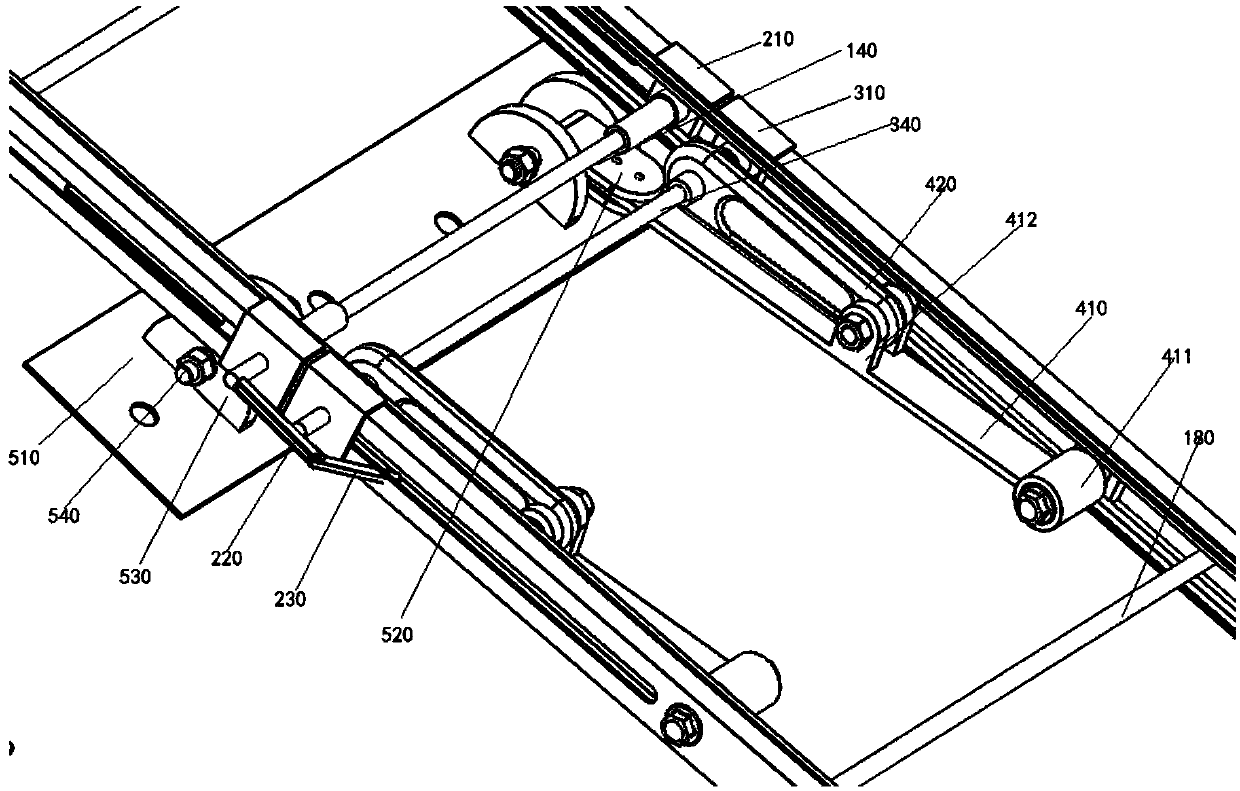
An adjustable mopping vehicle technology, applied in carpet cleaning, floor cleaning, manual floor scrubbing machinery, etc., can solve the problem of unsuitable environmental sanitation and cleaning work cost control, mopping vehicle steering is not flexible enough, cannot be widely used, etc. problem, to achieve the effect of light weight, convenient adjustment of handle and bracket position, and low cost

Pending Publication Date: 2019-04-05
JILIN UNIV
View PDF1 Cites 0 Cited by
  • Summary
  • Abstract
  • Description
  • Claims
  • Application Information

AI Technical Summary

Problems solved by technology

Ordinary mop The mop has a small contact area with the ground, and it is difficult to clean the ground in a large space at one time, so it is unwise to use an ordinary mop on this occasion
Therefore, electric mopping vehicles have been used for large-scale cleaning operations, but this significantly increases the cost and cannot be widely used, especially not suitable for areas where the cost control of sanitation and cleaning work is relatively strict.
[0003] In the patent No. CN 105595927 A "A Mopping Vehicle for Sanitation", the mopping vehicle for sanitation is too large in size, occupies a space, and is provided with a water tank. The rear part of the mopping vehicle does not lean forward during the mopping, but the disadvantages of this are: the weight of the mopping vehicle is obviously increased, and more physical strength will be consumed; the operation is inconvenient, and water needs to be filled and released; The water in the sink is easy to spill on the ground; in addition, the steering of the mopping vehicle is not flexible enough, so it is inconvenient to use in narrow spaces such as corridors

Method used


Image

  • Two-wheeled adjustable cleaning vehicle
  • Two-wheeled adjustable cleaning vehicle
  • Two-wheeled adjustable cleaning vehicle

Examples


Embodiment Construction

[0059] In order to make the purpose, technical solutions and advantages of the specific embodiments of the present invention more clear, the technical solutions in the embodiments of the present invention will be described in detail and completely in combination with the drawings in the embodiments of the invention. Based on the embodiments of the present invention, other embodiments obtained by persons of ordinary skill in the art without making creative efforts all belong to the protection scope of the present invention.

[0060] The invention provides a two-wheel adjustable floor mopping vehicle. The mopping vehicle includes a handrail part, a bracket part, a mop fixing plate part, a support rod, a mop cloth and a universal wheel part. Shaped slider stretching handle; the brackets on both sides are connected and fixed by several support rods, and the bottom of the bracket is fixedly connected with the universal wheel; the mop fixing plate is connected with the bracket throug...


PUM


Abstract

The invention discloses a two-wheeled adjustable cleaning vehicle. The two-wheeled adjustable cleaning vehicle comprises two upright columns, two through grooves, two first slide pieces, a first adjusting slide rod, a first hollow rod, two first brackets, two second bracket and a mop fixing plate, wherein a U-shaped groove is axially formed in opposite side surfaces of the upright columns; the twothrough grooves are axially formed in the bottom surfaces of the U-shaped groove in the upper parts of the corresponding upright columns; the two first slide pieces are of a U-shaped structure and glidingly arranged on the outer sides of the upright columns in a sleeving manner; the first adjusting slide rod is arranged between the two upright columns and two ends penetrate the through grooves and the first slide pieces respectively and are in threaded connection with the first slide pieces; one end of the first hollow rod is in threaded connection with one end of the first adjusting slide rod; one ends of the two first brackets are correspondingly hinged with the upright columns close to the bottoms of the through grooves respectively; one ends of the two second bracket are correspondingly hinged with the middles of the first brackets respectively, and the other ends are rotationally and correspondingly arranged on the first adjusting slide rod in a sleeving manner; the mop fixing plate is of a rectangular platy structure, and the other ends of the first brackets are hinged with the axial two sides of the mop fixing plate respectively.

Description

technical field [0001] The invention relates to the field of sanitation equipment, and more specifically, the invention relates to a two-wheel adjustable mopping vehicle. Background technique [0002] Nowadays, for places with relatively wide spaces such as squares, workshops, halls, and corridors, mopping the floor is a heavy workload and labor-intensive work. Ordinary mops have a small contact area with the ground, and it is difficult to clean the ground in a large space at one time, so it is unwise to use ordinary mops on this occasion. Therefore, electric mopping vehicles have been used for large-scale cleaning operations, but this significantly increases the cost and cannot be widely used, especially not suitable for areas where the cost control of sanitation and cleaning work is relatively strict. [0003] In the patent No. CN 105595927 A "A Mopping Vehicle for Sanitation", the mopping vehicle for sanitation is too large in size, occupies a space, and is provided with...

Claims


Application Information

Patent Timeline
Patent Type & Authority Applications(China)
IPC IPC(8): A47L11/28A47L11/40
CPCA47L11/28A47L11/40A47L11/4072
Inventor 陈书明梁超谷飞鸿吴开明陈文海
Owner JILIN UNIV
Learn More