

Self-cleaning dedusting monitor
A technology for monitors and control chips, applied in cleaning methods and appliances, cleaning methods using tools, chemical instruments and methods, etc., can solve the problems of increasing resource consumption, achieve resource consumption problems, save monitoring and operation links, Ease of use
Inactive Publication Date: 2019-04-05
贵州创世科技有限公司
View PDF7 Cites 16 Cited by
- Summary
- Abstract
- Description
- Claims
- Application Information
AI Technical Summary
Problems solved by technology
[0005] The present invention intends to provide a self-cleaning and dust-removing monitor to solve the technical problem that the existing self-cleaning monitor needs to be manually jacked up and connected to the power supply, which increases resource consumption
Method used
View moreImage
Smart ImageViewing Examples

Examples
Embodiment Construction
[0016] Further detailed explanation through specific implementation mode below:
Login to View More PUM
 Abstract
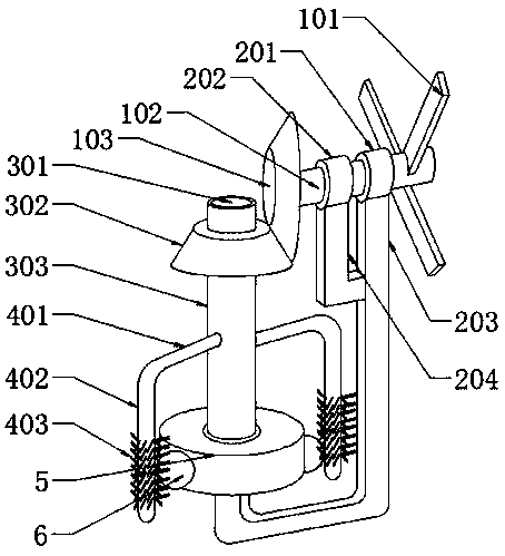
The invention discloses a self-cleaning dedusting monitor, and relates to the technical field of monitoring equipment. The self-cleaning dedusting monitor comprises a mounting seat, a brush, a power mechanism and a transmission mechanism. The power mechanism comprises a support arm. The lower end of the support arm is connected to the mounting seat, the upper end of the support arm is rotatably connected with a rotating shaft, one end of the rotating shaft is connected with a plurality of air wings, and the other end of the rotating shaft is fixedly connected with a driving bevel wheel. The transmission mechanism includes a ball bearing, a transmission shaft and a driven bevel wheel; the lower end of the transmission shaft is rotatably connected to the center of the mounting seat through the ball bearing, and the upper end of the transmission shaft and the driven bevel wheel are fixedly connected, and the driven bevel wheel meshes with the driving bevel wheel. The brush comprises a brush bar, the brush bar is provided with bristles, the brush bar is connected to the transmission shaft, and the bristles can be in contact with a camera. According to the scheme, the self-cleaning dedusting monitor utilizes the wind power existing in the outdoor natural environment as a power source for cleaning the camera, and solves the problem of resource consumption caused by the need of a power supply in the prior art.
Description
technical field [0001] The invention relates to the technical field of monitoring equipment, in particular to a self-cleaning and dust-removing monitor. Background technique [0002] With the continuous development of information technology and electronic technology, social security has become an issue that people attach great importance to when traveling. People pay attention to life safety and property safety. Therefore, monitoring equipment has also emerged leisurely with the development of information and electronic technology. , The monitor is also a kind of monitoring equipment, and the monitoring camera of the monitor plays a particularly important role in the development of public security work. The monitor is usually installed outdoors, and it is installed in a higher place above the ground. It mainly shoots the situation on the ground. However, because there are many vehicles and pedestrians passing by outdoors, and the dust concentration in the air is also high, s...
Claims
Login to View More Application Information
Patent Timeline
 IPC IPC(8): B08B1/00B08B1/04B08B13/00
CPCB08B13/00B08B1/12B08B1/32
Inventor袁勇
Owner贵州创世科技有限公司