Supercharge Your Innovation With Domain-Expert AI Agents!

Spiral model tear off method

A spiral type and car model technology, which is applied in the direction of turning equipment, turning equipment, metal processing equipment, etc., can solve the problem of not being able to respond to the removal of the inner sleeve or the outer sleeve, and achieve the effect of avoiding damage

Active Publication Date: 2020-08-11
SHENZHEN HUAYA CNC MASCH CO LTD
View PDF9 Cites 0 Cited by
  • Summary
  • Abstract
  • Description
  • Claims
  • Application Information

AI Technical Summary

Problems solved by technology

[0003] The technical problem to be solved by the present invention is to provide a method for tearing off a spiral vehicle to solve the problem that the prior art cannot take out the inner sleeve or the outer sleeve of the reactor irradiation alloy target tube

Method used


Image

  • Spiral model tear off method
  • Spiral model tear off method

Examples


Embodiment 1

[0022] The spiral car model tearing method is used to remove the inner sleeve embedded in the inner wall of the long tube, including the following steps:

[0023] Step 1. Clamp the long tube and drive the long tube to rotate; turn a spiral groove on the inner surface of the inner sleeve;

[0024] Step 2, clamping one end of the inner sleeve, gradually tearing along the groove bottom of the spiral groove, so that the inner sleeve is gradually separated from the long tube.

[0025] Further, the groove bottom wall thickness of the spiral groove is 0.05-0.3mm.

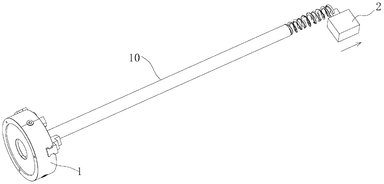
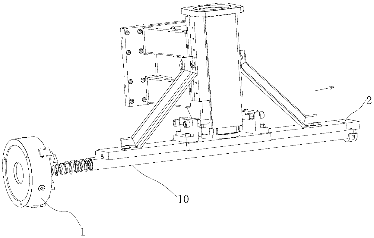
[0026] Further, in the step 1, the three-jaw chuck 1 of the lathe clamps one end of the long tube 10, and the support base or the traveling frame supports the other end of the long tube; the boring tool gradually extends into the long tube for turning. set.

[0027] Further, in the step 2, refer to figure 1 , the clamp 2 clamps the end of the inner sleeve far away from the chuck, and moves to the end far away from the t...

Embodiment 2

[0030] The spiral car model tearing method is used to remove the sleeve sleeved on the outer circle of the long shaft, including the following steps:

[0031] Step 1, clamping the long shaft, and driving the long shaft to rotate; turning a spiral groove on the outer surface of the sleeve;

[0032] Step 2, clamping one end of the shaft sleeve, gradually tearing along the groove bottom of the spiral groove, so that the shaft sleeve is gradually separated from the long axis.

[0033] Further, the groove bottom wall thickness of the spiral groove is 0.05-0.3mm.

[0034] Further, in the step 1, the three-jaw chuck of the lathe clamps one end of the long shaft, and the tailstock tip supports the other end of the long shaft.

[0035] Further, in the step 2, the end of the bushing away from the three-jaw chuck is clamped, and the bushing is gradually torn along the groove bottom of the spiral groove; when the bushing is torn, the long The shaft rotates, and the clamp holding the end...


PUM


Abstract

The invention discloses a spiral vehicle type tearing-off method used for removing a shaft sleeve sleeving a long shaft outer circle or an inner sleeve embedded in the inner wall of a long pipe. The method comprises the following steps that firstly, a long shaft or the long pipe is clamped and driven to rotate, and a spiral groove is turned in the outer surface of the shaft sleeve or the inner surface of the inner sleeve; and secondly, one end of the shaft sleeve or the inner sleeve is clamped, gradual tearing-off is conducted along the groove bottom of the spiral groove, the shaft sleeve is gradually separated from the long shaft, or the inner sleeve is gradually separated from the long pipe. The spiral groove is turned in the shaft sleeve sleeving a long shaft component, the shaft sleeveis gradually torn off along the groove bottom, and therefore the shaft sleeve can be gradually separated from the long shaft component, and long shaft component damage is avoided; accordingly a new shaft sleeve can be assembled on the long shaft component; and the spiral groove is turned in the inner wall of the inner sleeve of the long pipe component, and the inner sleeve is gradually torn off along the groove bottom.

Description

technical field [0001] The invention relates to the field of turning, in particular to a method for tearing off a spiral car model. Background technique [0002] At present, many long-axis parts will have an outer sleeve and a shaft sleeve, or an inner sleeve inlaid in the long tubular parts, or, an outer sleeve and a shaft sleeve of the pipe parts, and an inner sleeve will be embedded in the inner hole, for example Reactor irradiation alloy target tube; after a period of use of reactor irradiation alloy target tube, the outer sleeve and inner sleeve will be corroded and invalidated, so it is necessary to replace the inner sleeve and outer sleeve of the reactor irradiation alloy target tube, or to recycle the reactor irradiation For the middle part of the alloy target tube, since the inner sleeve and the outer sleeve are closely connected with the reactor irradiation alloy target tube body, it is impossible to take out the inner sleeve or the outer sleeve by ordinary methods...

Claims


Application Information

Patent Timeline
Patent Type & Authority Patents(China)
IPC IPC(8): B23B5/48B23B1/00
CPCB23B1/00B23B5/48
Inventor 代建东代志高任伯阶冯志权龚振豪
Owner SHENZHEN HUAYA CNC MASCH CO LTD
Features
  • R&D
  • Intellectual Property
  • Life Sciences
  • Materials
  • Tech Scout
  • Unparalleled Data Quality
  • Higher Quality Content
  • 60% Fewer Hallucinations
Learn More