Cutter linking mechanism of bookbinding machine

A linkage mechanism and binding machine technology, applied in binding, metal processing, etc., can solve the problems of affecting the reversing, the blades of the cutting knife are not separated, the reliability and precision are not high, so as to reduce the occupied space, avoid easy failure, The effect of high motion reliability

Pending Publication Date: 2019-04-05
南京泛恩科技有限公司
View PDF0 Cites 0 Cited by
  • Summary
  • Abstract
  • Description
  • Claims
  • Application Information

AI Technical Summary

Problems solved by technology

Its existing problems are: 1. Since the blade of the cutter is separated only by the extension spring 7 to drive the pull rod 3 and the shift fork 4, the pulling force of the extension spring 7 is easy to change or fail after repeated use, thus causing the blade of the cutter to be separated. The separation is not in place, affecting the fall of the plastic riveting tube 8 and the subsequent re-cutting of the tube
2. When the pin hook 104 at the lower end of the half shaft 105 rises and the other end of the rocker 6 has a small contact surface (basically a line contact) and does not match, it is prone to slipping, which affects the rotation of the rocker 6
3. There are many mechanical parts to complete the positive and negative reversing of the cutter, which takes up space and affects the reliability of the movement
4. The displacement accuracy of the semi-axis rise is not high, which affects the reversing and cutter movement accuracy
In short, there are many parts and the reliability and accuracy are not high

Method used


Image

  • Cutter linking mechanism of bookbinding machine
  • Cutter linking mechanism of bookbinding machine
  • Cutter linking mechanism of bookbinding machine

Examples


Embodiment

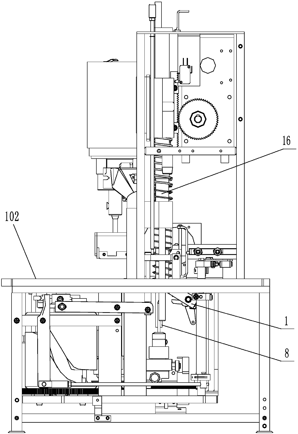
[0035] The binding machine of the present embodiment is as Figure 4 As shown, there are lower pressure riveting thimble 9, cutter assembly 10, lifting motor 11, lifting rack 13, upper pressure riveting mechanism 14, punching mechanism 15, lifting guide column 16, feeding mechanism 17, top plate 101, middle platform plate 102 and base plate 103 etc. The output end of the lifting motor 11 is provided with a gear 12 meshed with the lifting rack 13 .

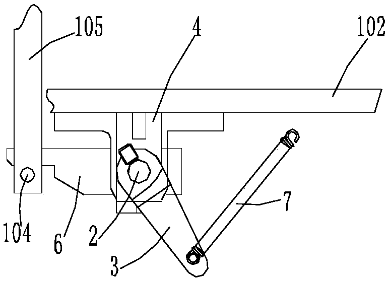
[0036] The cutter linkage mechanism of the binding machine of the present embodiment, such as Figure 4 and Figure 5 As shown, it includes a cutter assembly 10 and a linkage mechanism, and the linkage mechanism includes a lifting rack 13 and a reversing mechanism of the binding machine.

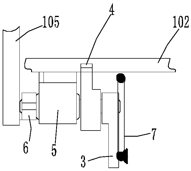
[0037] Such as Figure 6 As shown, the cutter assembly includes a knife rest 19 fixed on the middle platform 102 of the binding machine, a movable blade 18-1 and a stopper 18-2 fixed on the knife rest 19, and the knife edge 18-1 and the stopp...


PUM


Abstract

The invention relates to a cutter linking mechanism of a bookbinding machine and belongs to the technical field of permanent bookbinding of stacked paper or collating mark in bookbinding work. The cutter linking mechanism comprises a cutter component and a linking mechanism, wherein the cutter component comprises a cutting edge, a stop dog and a tool rest; the linking mechanism comprises a lifterrack and a reversing mechanism of the bookbinding machine; the reversing mechanism comprises a fixed seat fixed on a middle platen of the bookbinding machine and a rotary shaft running through the fixed seat; the bottom end of the lifter rack is provided with a pin shaft which is extended below the middle platen ; a shifting fork and a poking block respectively located on two sides of the fixed seat are additionally arranged on the rotary shaft in a penetrating manner; one end of the shifting fork is linked with the cutting edge; and the poking block is crescent and a pulley is arranged at oneend of the poking block. According to the cutter linking mechanism, parts of the reversing mechanism are reduced, reversing of the cutter is directly realized through the lifter rack of the bookbinding machine body, and the mechanism has higher operation reliability and precision.

Description

technical field [0001] The invention relates to a cutter of a full-automatic bookbinding machine and a linkage mechanism thereof, belonging to the technical field of permanent bookbinding of stacked papers or stickers in bookbinding operations. Background technique [0002] At present, the automatic binding machine used for the binding of paper such as reconciliation pages, bills, files, etc., this kind of binding machine realizes the automation of the binding process, as long as the binding document is placed on the workbench, and the corresponding operation is started through the operation panel, Several process steps such as punching, tube cutting and riveting binding can be completed at one time, which greatly simplifies the labor intensity and improves the binding quality. [0003] Existing fully automatic binding machines such as figure 1 As shown, the cutter mechanism 1 on it is fixed on the middle platform 102. Such as figure 2 and image 3 As shown, the cutter ...

Claims


Application Information

Patent Timeline
Patent Type & Authority Applications(China)
IPC IPC(8): B26D1/08B26D5/08B26D7/06B42B5/02
CPCB26D1/08B26D5/086B26D7/06B42B5/02
Inventor 周乐鹏
Owner 南京泛恩科技有限公司
Why Eureka
Try Eureka