
High-voltage grounding isolation switch and isolation method

A technology for grounding isolating switches and high-voltage isolating switches, which is applied in the direction of grounding switches, electric switches, and high-voltage air circuit breakers. No contact resistance, good safety effect

Pending Publication Date: 2021-10-22
HANGZHOU YONGDE ELECTRIC APPLIANCES
View PDF1 Cites 0 Cited by
  • Summary
  • Abstract
  • Description
  • Claims
  • Application Information

AI Technical Summary

Problems solved by technology

[0003] The purpose of the present invention is to overcome the disadvantages of the current isolating switch gear transmission mechanism, such as complex structure, easy detachment, poor three-phase linkage performance, and troublesome assembly and maintenance, and provide a transmission mechanism with simple and reliable structure and three-phase linkage performance. High-voltage grounding disconnector and isolation method with high quality and convenient assembly and maintenance

Method used


Image

  • High-voltage grounding isolation switch and isolation method
  • High-voltage grounding isolation switch and isolation method
  • High-voltage grounding isolation switch and isolation method

Examples


Embodiment Construction

[0021] The present invention will be further described below in conjunction with the accompanying drawings.

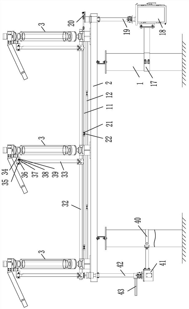
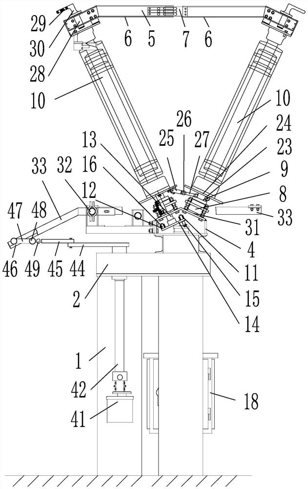
[0022] as attached figure 1 , attached figure 2 , attached image 3 , attached Figure 4 Shown: a high-voltage grounding isolating switch, including: a frame 2 with a plurality of pillars 1, three main knife devices 3 arranged horizontally, a main knife driving device, and a ground knife device. The main knife device 3 includes: mounted on The transmission seat 4 on the frame 2, two main knife assemblies arranged in front and back, two side ends are provided with grooves 5 and correspond to the two main knife assemblies one by one, and the thickness is adapted to the width of the grooves 5 Conductive block 7, knife bar linkage device; main knife assembly includes: bearing seat 8 mounted on the transmission seat 4, the lower end is provided with the insulating column 10 of the installation shaft 9 pivotally connected with the bearing seat 8 through the bearing; two ...


PUM


Abstract

The invention relates to a high-voltage grounding isolation switch, which comprises a rack provided with a plurality of supporting columns, three transversely arranged main knife devices, a main knife driving device and a grounding knife device. Each main knife device comprises a transmission seat arranged on the rack; two main knife assemblies arranged front and back; two cutter bars, wherein one side end of each cutter bar is provided with a groove, and the cutter bars correspond to the two main cutter assemblies in a one-to-one mode; conductive clamping blocks, wherein the thickness of each conductive clamping block is matched with the width of the corresponding groove; and a cutter bar linkage device. The main knife assembly comprises a bearing seat mounted on the transmission seat and an insulating column of which the lower end is provided with a mounting shaft pivoted with the bearing seat; one ends of the two cutter bars are connected with the upper ends of the insulating columns of the two main cutter assemblies in a one-to-one correspondence manner; one end of the conductive clamping block is positioned in the groove of one cutter bar and is connected with one cutter bar; when the isolation switch is powered on, the other ends of the conductive clamping blocks are clamped with the grooves of the other cutter bars; and the cutter bars are made of a U-shaped aluminum profile. According to the high-voltage grounding isolation switch, the transmission mechanism is simple and reliable in structure, the three-phase linkage performance is good, and assembly and maintenance are convenient.

Description

technical field [0001] The invention relates to the field of power facility accessories, in particular to a high-voltage grounding isolating switch and an isolating method. Background technique [0002] Isolating switch is a kind of outdoor high-voltage electrical equipment, which is used for switching high-voltage lines under no-load conditions, or electrically isolating electrical equipment such as high-voltage busbars and short circuits to be repaired from live high-voltage lines. Chinese patent 03218090 discloses a kind of anti-corrosion three-phase linkage high-voltage switch, which is equipped with a sector gear at the lower end of the insulating column, and meshes in the transmission box to form a gear transmission structure. The high-voltage switch is a kind of isolating switch; the high-voltage switch rotates the insulating column through gear transmission to achieve switch closure, and drives one of the insulating columns to rotate through the driving device to dri...

Claims


Application Information

Patent Timeline
Patent Type & Authority Applications(China)
IPC IPC(8): H01H31/02H01H31/00H01H3/46H01H9/52H01H1/58H01H3/38H01H3/40
CPCH01H31/02H01H31/003H01H3/46H01H9/52H01H1/58H01H3/40H01H3/38
Inventor 冯为国沃金华
Owner HANGZHOU YONGDE ELECTRIC APPLIANCES
Learn More