Displaceable hinge unit

a technology of hinge unit and hinge, which is applied in the direction of pin hinges, door/window fittings, constructions, etc., can solve the problems of difficult re-adjustment of coupling position, mis-accuracy of conventional door hinge opening and closing position between the doors, etc., and achieves improved accuracy in opening and closing the door, stable maintenance, and easy movement

Active Publication Date: 2022-05-12
NA SUNG HO
View PDF17 Cites 0 Cited by
  • Summary
  • Abstract
  • Description
  • Claims
  • Application Information

AI Technical Summary

Benefits of technology

[0014]According to the present disclosure, the shaft is rotatably disposed on the outer frame and the inner frame is easily moved in one direction by rotating the shaft. Accordingly, regardless of coupling preciseness of the hinge unit with respect to a door or a storage body or displacement of a door in response to use of the door, accuracy in opening and closing the door can be improved by displacing a position of the door.
[0015]According to the present disclosure, the inner frame is realized in the form of a bearing, so that movement of the first housing for rotation and position adjustment of the second housing in response to opening and closing of the door is separately performed. A position of the door corrected by movement of the first housing may be stably maintained.

Problems solved by technology

However, the conventional door hinge may have a problem of mis-accuracy in opening and closing position between the door and the storage body as time passes due to incorrect initial coupling position of the outer frame and the inner frame or door weight, etc.
When such a problem occurs, the conventional door hinge has inconvenience of requiring readjustment of a bolting position, and even in a welded door hinge, re-adjustment of a coupling position is difficult.

Method used


Image

  • Displaceable hinge unit
  • Displaceable hinge unit
  • Displaceable hinge unit

Examples


Embodiment Construction

[0019]Hereinbelow, a preferred embodiment of the present disclosure will be described in detail with reference to accompanying drawings.

[0020]Unless otherwise defined, all terms including technical and scientific terms used herein have the same meaning as commonly understood by one of ordinary skill in the art to which the present disclosure belongs. When terms used herein are different from the commonly understood meaning, the terms will be interpreted as defined herein.

[0021]However, the terminology used herein is for the purpose of describing embodiments of the present disclosure only and the scope and spirit of the present disclosure are not limited to the embodiment described hereinbelow. The same reference numerals will be used throughout the description to refer to the same or like parts.

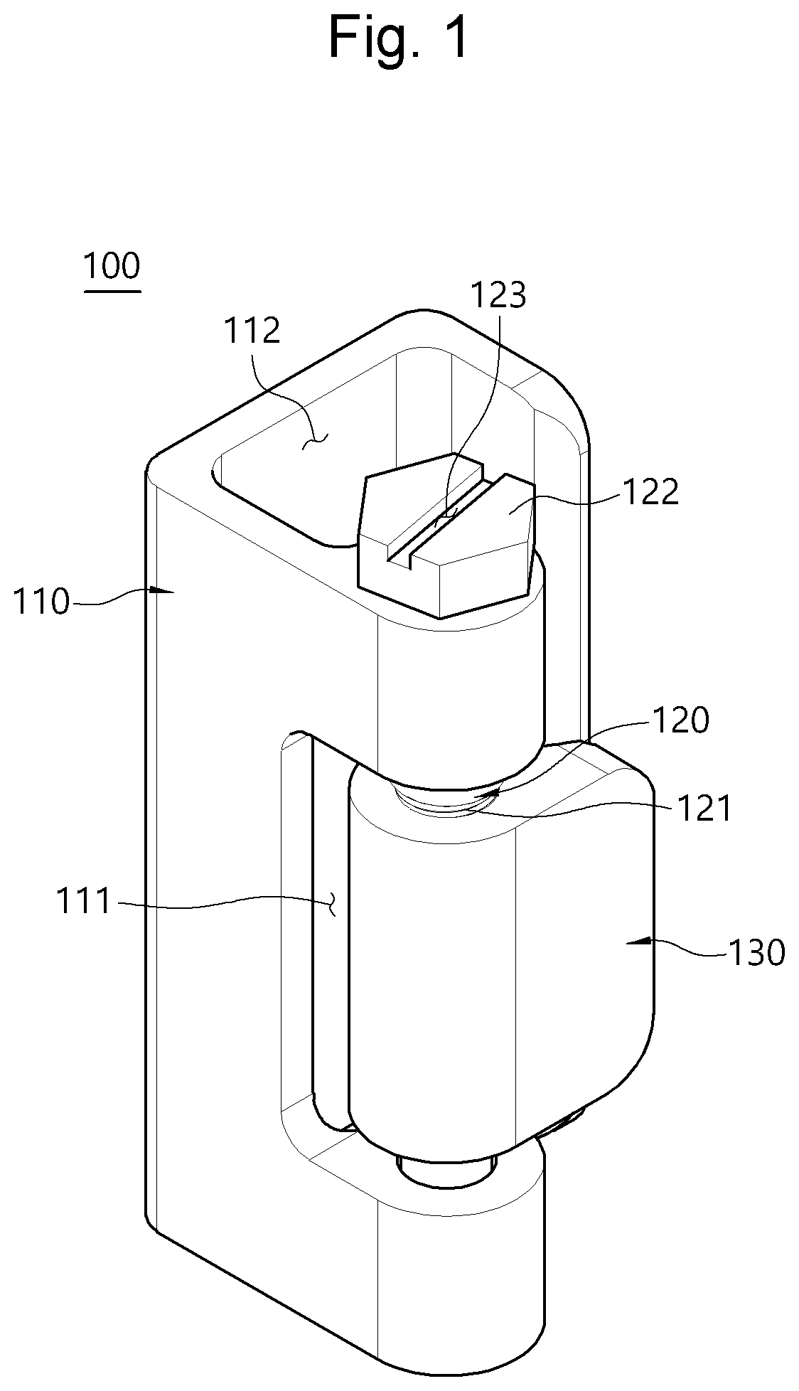
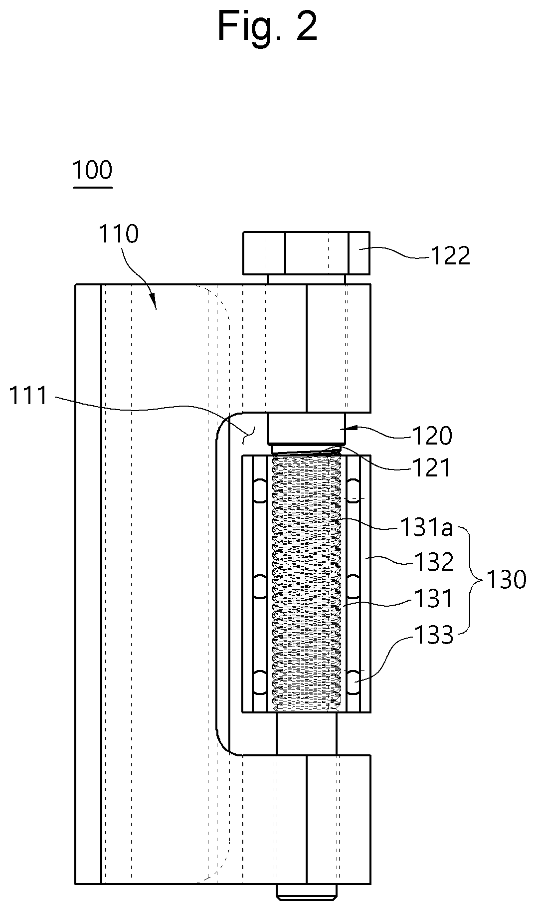
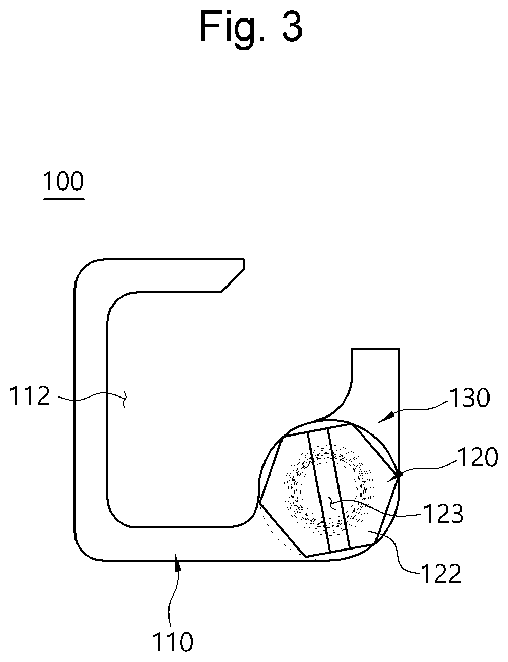
[0022]FIG. 1 is a perspective view showing a displaceable hinge unit according to an embodiment of the present disclosure. FIG. 2 is a side sectional view showing the displaceable hinge unit ...


PUM


Abstract

A displaceable hinge unit is provided. The displaceable hinge unit includes: an outer frame having an insertion groove formed on a longitudinal center portion of a first lateral surface thereof; a shaft rotatably disposed in the outer frame by passing through the insertion groove of the outer frame, and having a screw thread formed on an outer circumferential surface thereof located in the insertion groove; and an inner frame having a screw thread that is formed on an inner circumferential surface thereof and is engaged with the screw thread of the shaft, and configured to form translational motion in the insertion groove by means of rotation of the shaft.

Description

TECHNICAL FIELD[0001]The present disclosure relates to a displaceable hinge unit capable of easily realizing position adjustment of a door coupled to a door frame.BACKGROUND ART[0002]A door is connected to a storage body or an interior space that is open at one surface to open and close the storage body or the interior space by a door hinge.[0003]The door hinge may be realized in various shapes, and include: an outer frame coupled to the storage body or the interior space; an inner frame coupled to the door; and a shaft disposed by passing through the outer frame and the inner frame.[0004]As an example, Korean Patent No. 10-1947919 (Title of invention: Door hinge with semi-automatic closer function and stopper function) proposes a door hinge. Although names are different from as described above, the door hinge includes an outer hinge frame, an inner hinge frame, and a shaft.[0005]In the conventional door hinge, the outer frame and the inner frame may be respectively coupled to the s...

Claims


Application Information

Patent Timeline
Patent Type & Authority Applications(United States)
IPC IPC(8): E05D7/04E05F3/20
CPCE05D7/0423E05D2700/02E05D2007/0469E05F3/20E05D3/02E05D7/0027E05Y2201/628E05Y2600/314E05Y2600/324E05Y2900/10E05D7/04E05Y2600/32E05Y2900/132
Inventor NA, SUNG HO
Owner NA SUNG HO
Why Eureka
Try Eureka