Pedal lever ratio adjusting control method and system

A technology for adjusting control and leverage ratio, which is applied in the direction of brakes, brake components, transportation and packaging, etc., can solve the problems of time-consuming and laborious, manual adjustment, waste of matching time, etc., to ensure driving safety, save matching time, and overcome time-consuming strenuous effect

Active Publication Date: 2019-04-05
GREAT WALL MOTOR CO LTD
View PDF10 Cites 1 Cited by
  • Summary
  • Abstract
  • Description
  • Claims
  • Application Information

AI Technical Summary

Problems solved by technology

In the prior art, the lever ratio of the brake pedal is mostly non-adjustable structure, and the position of the pedal will change when the lever ratio is adjusted for a small number of brake pedals with adjustable lever ratio, and manual adjustment is required. The adjustment process is time-consuming and laborious. Among them, the lever ratio is the ratio of the distance from the rotation axis of the brake pedal arm to the shift fork and the distance from the rotation axis of the brake pedal arm to the brake pedal. There are many technical problems in the above structure:
[0003] (1) The lever ratio of the brake pedal cannot be adjusted. During the braking performance matching test, the pedal feel needs to be evaluated. If the pedal feel is poor, it is necessary to replace the pedal with a different lever ratio and try again, which wastes matching time. Without optimal pedal feel
[0004] (2) The lever ratio of the brake pedal is not adjustable. If the pedal feels poor, the pedal needs to be replaced again. It cannot be adjusted according to individual differences of different drivers, and the universal performance is poor.
[0005] (3) The lever ratio of the brake pedal can be adjusted. Since the position of the brake pedal changes, and the height of the brake pedal and the height of the accelerator pedal are required to be checked by man-machine in the design of the car, the lever ratio can be adjusted. Changing the position of the brake pedal will affect people's driving safety

Method used


Image

  • Pedal lever ratio adjusting control method and system
  • Pedal lever ratio adjusting control method and system
  • Pedal lever ratio adjusting control method and system

Examples


Embodiment 1

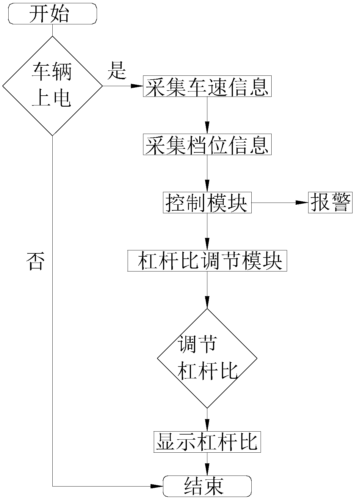
[0061] This embodiment relates to a pedal lever ratio adjustment control method, combining figure 1 As shown, it includes the following steps:

[0062] Step s1: power on the vehicle;

[0063] Step s2: start the leverage ratio adjustment function;

[0064] Step s3: Collect vehicle speed information and gear position information, and judge whether the vehicle speed information and gear position information meet the requirements; in this step, if the vehicle speed is equal to 0km / h, the vehicle speed information meets the requirements; if the gear position is in P or neutral, the gear position The information meets the requirements, and if the vehicle speed information and gear position information do not meet the requirements, an alarm will be issued.

[0065] Step s4: If the vehicle speed information and the gear position information meet the requirements, then drive the pivot shaft of the pedal arm to slide to change the position of the pivot shaft relative to the body, and ...

Embodiment 2

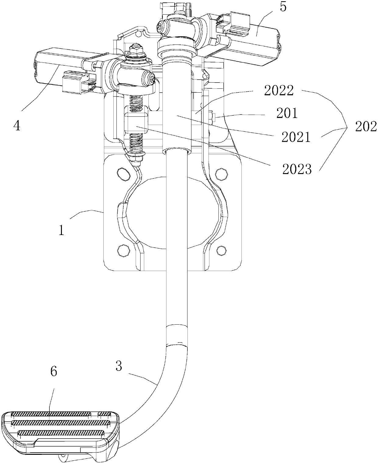
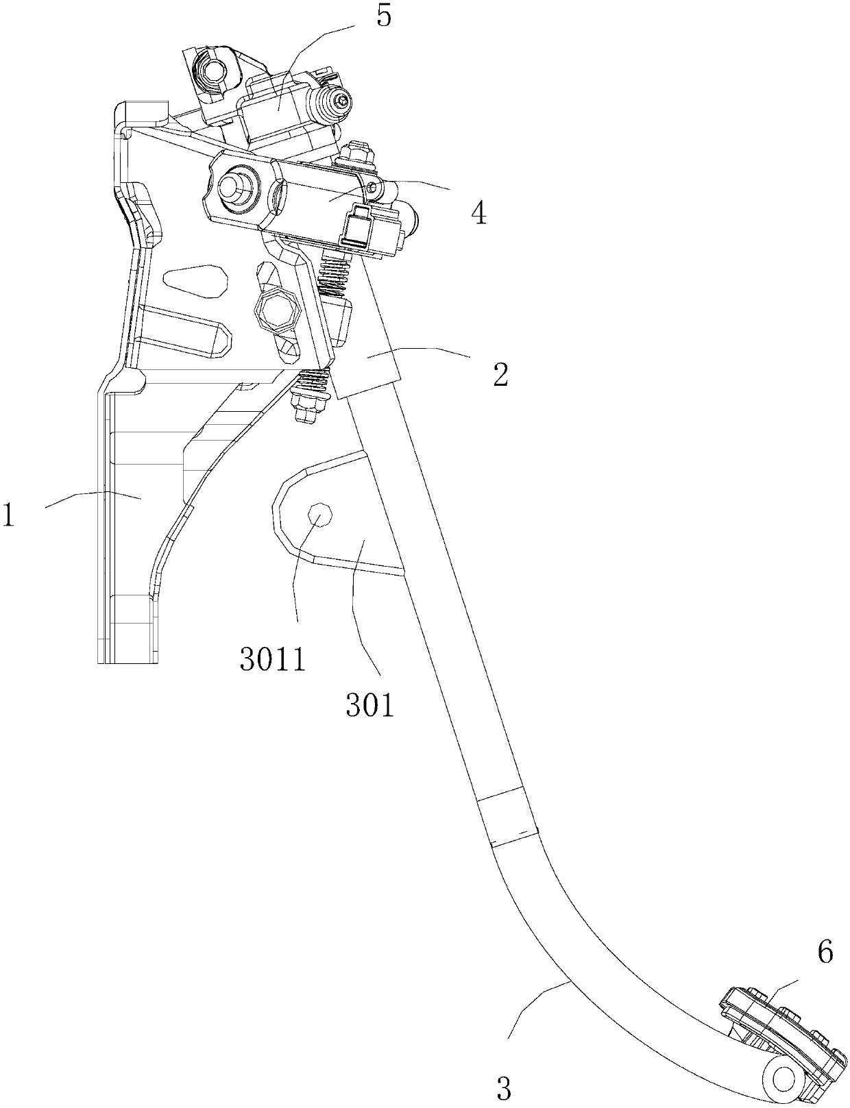
[0070] This embodiment relates to a pedal lever ratio adjustment control system for realizing the pedal leverage ratio adjustment function, mainly including a control module and a switch module connected to the control module, a data acquisition module and a leverage ratio adjustment module, wherein the switch module Used to start the control module, the data acquisition module is used to collect vehicle speed information and gear information, and the lever ratio adjustment module is used to drive the pivot shaft of the pedal arm to slide to change the position of the pivot shaft relative to the body and keep the pedal relative The position of the vehicle body remains unchanged, and the lever ratio of the pedal is adjusted.

[0071] In this embodiment, the switch module can be a structure in the prior art, which is used to input the driver's instruction information, so that the control module starts the lever ratio adjustment function; the control module can be a controller or ...


PUM


Abstract

The invention provides a pedal lever ratio adjusting control method and system. The control method includes the following steps: powering a vehicle on; starting a lever ratio adjusting function; collecting and judging whether speed information and shift information accord with requirements; driving a pivot shaft of a pedal arm to slide if the speed information and the shift information accord withthe requirements; changing the position of the pivot shaft corresponding to a vehicle body; keeping the position of a pedal corresponding to the vehicle body unchanged; and adjusting the lever ratioof the pedal. The control method can adjust the lever ratio of the pedal and keep the position of the pedal corresponding to the vehicle body unchanged, so that the time-consuming and labor-consumingdeficiencies of manually adjusting can be overcome, matching time can be saved, and optimal pedal feelings can be realized; and the control method is suitable for adjusting with the individual difference of drivers, so that the method is good in universality, and can effectively guarantee the driving safety of the drivers.

Description

technical field [0001] The invention relates to the technical field of automobiles, in particular to a pedal lever ratio adjustment control method and a pedal lever ratio adjustment control system based on the pedal lever ratio adjustment control method. Background technique [0002] In the field of automobile chassis parts manufacturing technology, the brake pedal is used for deceleration and parking, and the frequency of use is very high. Its performance directly affects the driving safety of the car. The braking of the car is realized by stepping on the brake pedal, and the pedal produces a certain reaction force on the foot at the same time. With the improvement of driving comfort requirements, the requirements for brake pedal feel are also continuously improved when braking. In the prior art, the lever ratio of the brake pedal is mostly non-adjustable structure, and the position of the pedal will change when the lever ratio is adjusted for a small number of brake pedal...

Claims


Application Information

Patent Timeline
Patent Type & Authority Applications(China)
IPC IPC(8): B60T7/06B60T17/00
CPCB60T7/06B60T17/00
Inventor 张昭强张吉冯晓宇吴斌刘乐
Owner GREAT WALL MOTOR CO LTD
Why Eureka
Try Eureka