Conveying structure

A conveyor belt and sliding frame technology, applied in the direction of conveyor objects, transportation and packaging, etc., can solve the problems of large space occupied by telescopic devices, low work efficiency, and uncompact structure, and achieve compact conveying structure, fast movement, and convenience The effect of connection

Pending Publication Date: 2019-04-05
HUAXIAO PRECISION SUZHOU
View PDF0 Cites 2 Cited by
  • Summary
  • Abstract
  • Description
  • Claims
  • Application Information

AI Technical Summary

Problems solved by technology

[0005] If the above-mentioned conveying structure realizes driving the equipment to be conveyed to slide forward for a distance of 3L, four sliders must be installed, and the fourth-stage slider may not be provided with a timing belt, but at least three stages of timing belts are required to drive the waiting equipment. The conveying equipment moves forward with a distance of 3L, so that the space occupied by the telescopic device in the height direction is large and the structure is not compact; at the same time, the three-stage synchronous belt is driven and slid in sequence, which makes the conveying time of the telescopic device long and the working time is long. low efficiency

Method used


Image

  • Conveying structure
  • Conveying structure
  • Conveying structure

Examples


Embodiment 1

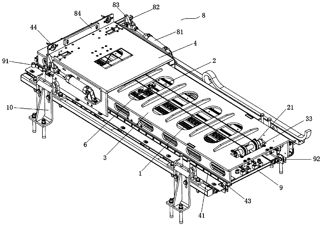
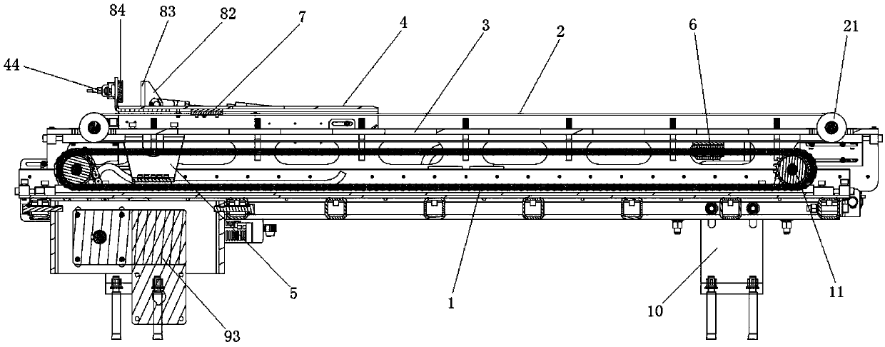
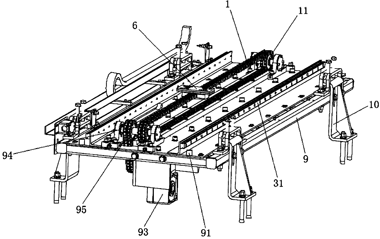
[0064] This embodiment provides a transport structure, such as figure 1 As shown, it includes a base 9 , a first conveyor belt 1 , a second conveyor belt 2 , a first sliding frame 3 and a second sliding frame 4 . Wherein the first conveyor belt 1 and the second conveyor belt 2 are respectively closed and looped on the respective corresponding roller sets, and the second conveyor belt 2 is stacked on the top of the first conveyor belt 1 at the required interval, and the second conveyor belt 2 The lower end is fixedly connected with the upper end of the first conveyor belt 1, the first conveyor belt 1 is driven by the first driver 93 to reciprocate and slide, the first carriage 3 is fixed on the lower end of the first conveyor belt 1, and the second conveyor belt 2 is wound around The second roller group 21 is fixed on the first sliding frame 3, the second sliding frame 4 is fixed on the upper end of the second conveyor belt 2, and the first sliding frame 3 is at the junction of...


PUM


Abstract

The invention provides a conveying structure. The conveying structure comprises a first conveying belt, a second conveying belt, a first slide frame and a second slide frame. The first slide frame isfixed to the lower end of the first conveying belt; the upper end of the first conveying belt is fixed to the lower end of the second conveying belt; the second slide frame is fixed to the upper end of the second conveying belt; the first conveying belt rotates anticlockwise to enable the lower end of the first conveying belt to move to the right by a distance L, and the whole of the first slide frame and the second slide frame is driven to move to the right by a distance L; due to the own action of the conveying belts, and the junction of the upper end of the first conveying belt and the lower end of the second conveying belt moves to the left by a distance L; the junction of the upper end of the first conveying belt and the lower end of the second conveying belt moves to the left by a distance 2L from an initial position and relative to the second conveying belt, and meanwhile, the second slide frame moves to the right by a distance 2L on the first slide frame along with the second conveying belt; and therefore, when the first conveying belt moves to the right by a distance L, the second slide frame moves to the right by a distance 3L relative to the initial position. The conveying structure is compact, and rapid in movement.

Description

technical field [0001] The invention belongs to the technical field of mechanical equipment, and in particular relates to a conveying structure. Background technique [0002] With the rise of China's manufacturing technology, the production efficiency of enterprises has developed rapidly, and the production lines of enterprises have also quietly transitioned from fixed lines that can only produce one product to flexible production lines with strong adaptability. Due to the influence of the equipment layout in the factory, the process of loading materials from the offline to the online supply of the material truck is relatively slow. At home and abroad, we have been looking for mechanized and intelligent handling technology and equipment to reduce the cost of handling and improve the efficiency of logistics and transportation. In this case, it is particularly necessary to carry out research on a fast loading and unloading conveying structure for material trucks. [0003] Fo...

Claims


Application Information

Patent Timeline
Patent Type & Authority Applications(China)
IPC IPC(8): B65G47/64
CPCB65G47/642
Inventor 刘晓静陈磊颜东
Owner HUAXIAO PRECISION SUZHOU
Why Eureka
Try Eureka