
Automatic clamping and transferring equipment of chuck clamp of lacquer round plate

A technology for transferring equipment and chucks, which is applied in the direction of transportation and packaging, conveyor objects, etc. It can solve the problems of material loss, contact surface reduction, slipping plates and falling on the ground, etc., and achieve the effect of low cost and simple mechanical structure

Active Publication Date: 2019-04-05
乐钢(天津)科技有限公司
View PDF8 Cites 2 Cited by
  • Summary
  • Abstract
  • Description
  • Claims
  • Application Information

AI Technical Summary

Problems solved by technology

[0004] Aiming at the deficiencies in the prior art, the purpose of the present invention is to provide an automatic clamping and transferring device for the chuck clamping of the lacquered circular plate, so as to solve the problems caused by the smoothness of the lacquered surface and the The round surface is combined so that when the pneumatic alloy jaws are close to the surface of the plate, the jaws need to seal the alloy block to prevent air leakage, and the hard polished surface of the alloy plate and the painted surface will form slippery, resulting in slippage if the plate is clamped and transferred vertically. When the plate hits the ground, it will cause material damage such as paint falling off the rounded corners and breaking of the thin plate. The groove surface of the single jaw structure is not suitable for the side arc edge of the painted round plate, which will cause a tangential contact surface. Reduce the situation, so that during the plate transfer operation, there will be a lot of material loss due to insufficient matching of parts

Method used


Image

  • Automatic clamping and transferring equipment of chuck clamp of lacquer round plate
  • Automatic clamping and transferring equipment of chuck clamp of lacquer round plate
  • Automatic clamping and transferring equipment of chuck clamp of lacquer round plate

Examples


Embodiment Construction

[0027] In order to make the technical means, creative features, goals and effects achieved by the present invention easy to understand, the present invention will be further described below in conjunction with specific embodiments.

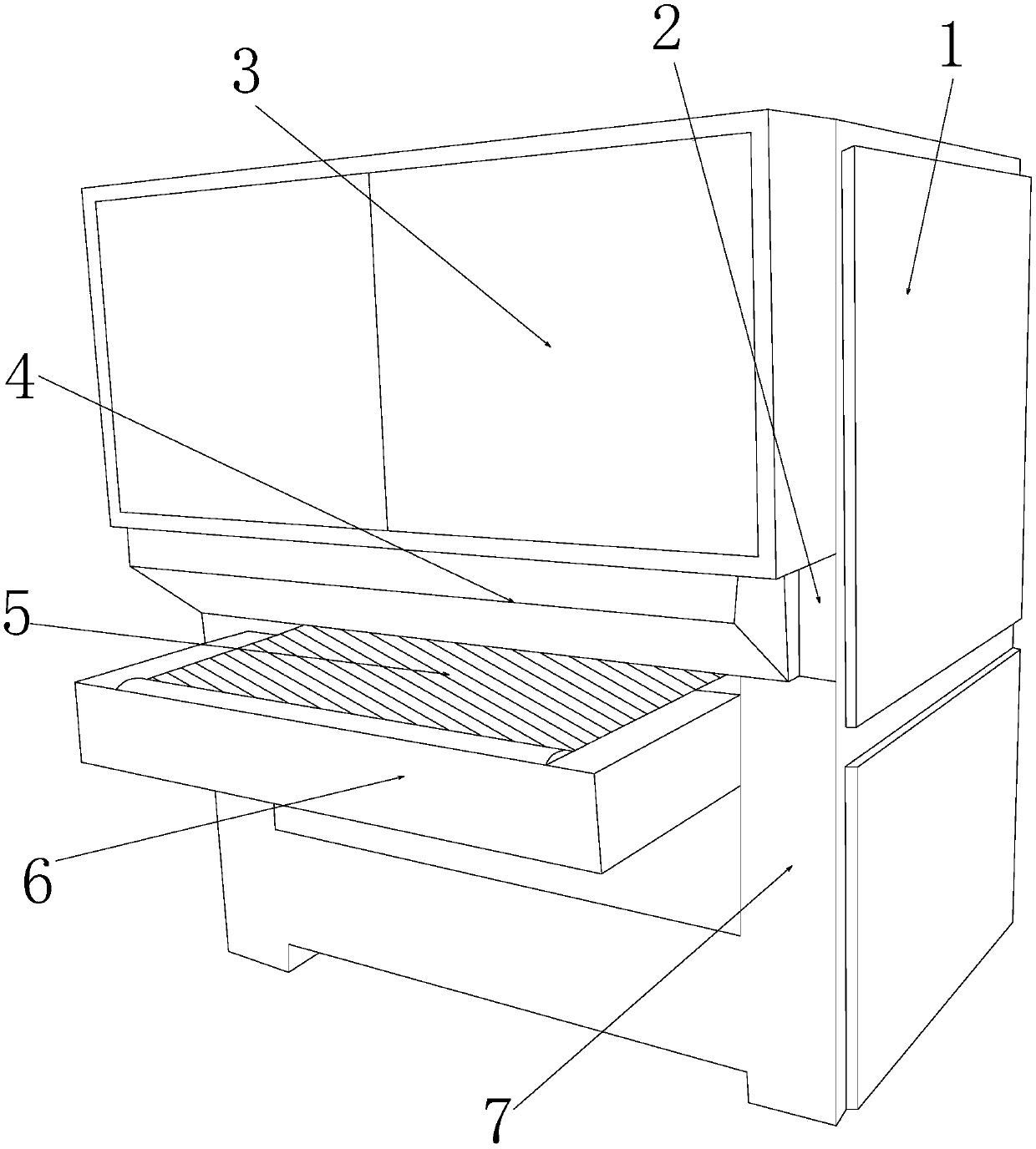
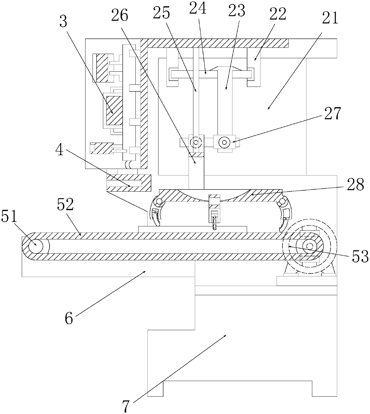
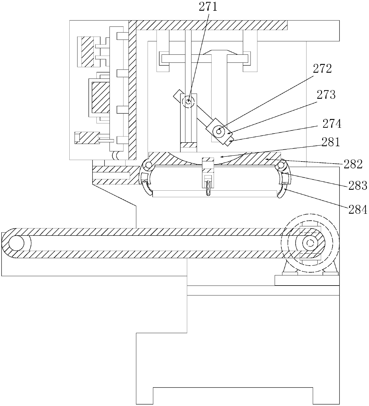
[0028] see Figure 1-Figure 6, the present invention provides an automatic clamping and transferring device for clamping and clamping round lacquered plates. Transmission linkage mechanism 5, pallet groove 6, concave base 7, the bottom of the chuck hanger box 2 and the top surface of the transmission linkage mechanism 5 adopt clearance fit, and the chuck hanger box 2 is welded on the electric control box 3, the top surface of the buffer ladder block 4 is close to the bottom surface of the electric control box 3, the pallet groove 6 is nested under the bottom of the front end of the transmission linkage mechanism 5, and the pallet groove 6 Inserted on the front side of the concave base 7 and welded into one, the chuck hanger box 2 communicates wit...


PUM


Abstract

The invention discloses automatic clamping and transferring equipment of a chuck clamp of a lacquer round plate. The automatic clamping and transferring equipment structurally comprises side baffles,a chuck hanging frame box, an electric control box, a buffer halfpace block, a conveying linkage mechanism, a supporting table groove and a U-shaped base; and the bottom of the chuck hanging frame boxis in clearance fit with the top face of the conveying linkage mechanism, and the chuck hanging frame box is welded to the rear side of the electric control box. A shaft wheel lifting frame is applied to be matched with a four-claw chuck, diaphragm face arc claw blocks downwards slide through short sliding rail groove frames, a three-claw chuck is emulated at the bottom of a chuck frame ring to form a reverse buckle effect that a round surface low lining is close to the plate, and corrugated diaphragms downwards slide in the four directions of the front end, the rear end, the left end and theright end in a matched mode to be attached to round edges to form the effect of edge side end wrapping; and then an arc groove disc seat is matched with a sleeve wheel bearing seat to rotate to drivea lifting strip plate to transfer the plate to ascend and descend, a workbench is subjected to moving protection on a plate production assembly line, the cost is low, a mechanical framework is simple, and the effects of protecting and guaranteeing the material quality are achieved.

Description

technical field [0001] The invention relates to an automatic clamping and transferring device for clamping a round plate with a painted surface, and belongs to the field of plate transferring equipment. Background technique [0002] The processing of plates requires steps such as cutting, grinding, polishing, painting, handling, and boxing. The overall engineering volume of plate assembly line processing is a trend of steady improvement. Contemporary factories all follow such a set of production methods for smooth connection operation. , autonomous processing by automated integrated equipment, combined with artificial intelligence to achieve labor-saving effects, but the handling of circular plates after painting will have a certain deviation in equipment matching. The shortcomings of the current technology that need to be optimized are: [0003] After the round plate is painted, due to the combination of the smoothness of the paint surface and the round surface, when the pn...

Claims


Application Information

Patent Timeline
IPC IPC(8): B65G47/90
CPCB65G47/90
Inventor 庄程芸
Owner 乐钢(天津)科技有限公司
Learn More