
Energy-dissipation flow channel structure capable of reducing flow speed

A flow channel and energy dissipation technology, applied in hydropower stations, marine engineering, coastline protection, etc., can solve the problems of disordered flow, cavitation erosion, poor flow conditions, etc. , the effect of improving hydraulic conditions

Pending Publication Date: 2019-04-05
CHINA POWER CONSRTUCTION GRP GUIYANG SURVEY & DESIGN INST CO LTD +2
View PDF5 Cites 1 Cited by
  • Summary
  • Abstract
  • Description
  • Claims
  • Application Information

AI Technical Summary

Problems solved by technology

At present, there is a common shortcoming in various forms of energy dissipation in the cave body. When the water flow passes through the cave body for energy dissipation, the flow state is disordered and the water flow condition is poor. Cavitation and cavitation are prone to occur in the contact part.

Method used


Image

  • Energy-dissipation flow channel structure capable of reducing flow speed
  • Energy-dissipation flow channel structure capable of reducing flow speed
  • Energy-dissipation flow channel structure capable of reducing flow speed

Examples


Embodiment Construction

[0020] The technical solution of the present invention is further described below in conjunction with the accompanying drawings, but the scope of protection is not limited to the description.

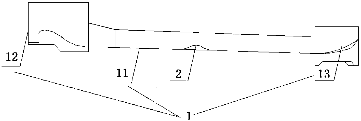
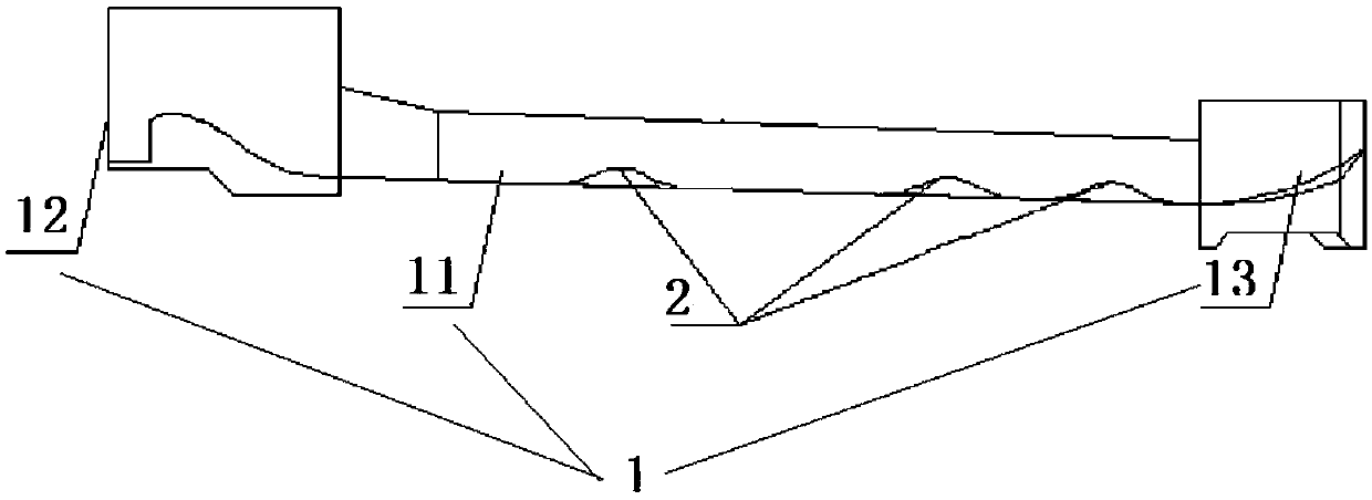
[0021] An energy-dissipating channel structure that reduces the flow rate of the present invention, such as figure 1 , figure 2 , image 3 , Figure 4 As shown, the flow channel hole 1 is included, and the flow channel surface 11 for the fluid to flow is arranged on the flow channel hole 1. One end of the flow channel surface 11 is provided with a flow channel inlet 12, and the other end of the flow channel surface 11 is provided with a flow channel surface. At least one hump weir 2 is arranged on the channel outlet 13 and the channel surface 11 .

[0022] By adopting the technical solution of the present invention, by setting a plurality of hump weirs on the flow channel surface, these hump weirs have different shapes, heights and sizes, and are arranged in a staggered manner on th...


PUM


Abstract

The invention discloses an energy-dissipation flow channel structure capable of reducing flow speed. The energy-dissipation flow channel structure comprises a flow channel hole, a flow channel face isarranged on the flow channel hole, a flow channel inlet is formed in one end of the flow channel face, a flow channel outlet is formed in the other end of the flow channel face, and hump weirs are arranged on the flow channel face. According to the technical scheme, multiple hump weirs are arranged on the flow channel face, have different shapes, heights and sizes, and are staggered on the flow channel face, so that after fluid flows past the hump weirs, a good flow state is maintained, the phenomenon of turbulence of the flow state of the fluid is reduced, and the hydraulic condition is improved; meanwhile, sudden shrinkage and sudden expansion of the overflow cross section are caused by the hump weirs, the energy loss of water current is increased, the purposes of reducing the flow speed and adjusting the flow line and the flow state are achieved, and the probability that the fluid suffers from cavitation damage in the flow channel hole is reduced. The energy-dissipation flow channel structure has the advantages of being simple, convenient in construction, low in building cost and the like, and is suitable for various sluicing structures which need energy dissipation treatment.

Description

technical field [0001] The invention specifically relates to the technical field of flow channel flood discharge and energy dissipation in water conservancy and hydropower projects, in particular to an energy dissipation channel structure for reducing flow velocity. Background technique [0002] As the flow channels set up in water conservancy and hydropower projects, in addition to meeting the flood discharge capacity, they should also ensure the safety of the flood discharge structures during operation, be well connected with the original river flow, and be able to give full play to the due energy dissipation effect to avoid discharge. The water flow caused scour damage to the downstream river bed and bank slope. The current energy dissipation design of the spillway generally adopts energy dissipation methods other than the exit. In recent years, the design of the energy dissipation structure of the spillway tunnel body has gradually developed, and various energy dissipati...

Claims


Application Information

Patent Timeline
Patent Type & Authority Applications(China)
IPC IPC(8): E02B8/06E02B9/02
CPCE02B8/06E02B9/02Y02E10/20
Inventor 杨家修孙卫杜帅群陈江杨萍湛正刚郑雪玉鲍伟
Owner CHINA POWER CONSRTUCTION GRP GUIYANG SURVEY & DESIGN INST CO LTD
Learn More