A high-pressure mud manifold and its application method

A mud and manifold technology, applied in the field of oil drilling, can solve the problems of inhuman design, inconvenient use, high labor intensity, etc., and achieve the effect of meeting explosion-proof and safety requirements, reducing labor intensity, and improving shock absorption effect.

Active Publication Date: 2022-02-25
DONGYING XIN HUALIAN PETROLEUM MACHINERY
View PDF6 Cites 0 Cited by
  • Summary
  • Abstract
  • Description
  • Claims
  • Application Information

AI Technical Summary

Problems solved by technology

At present, although the high-pressure mud circulation manifold is guaranteed in terms of pressure bearing capacity, the design is often not humane enough, and there are problems such as inconvenient use and large vibration.
In addition, most of the valves in the valve group are manual valves, requiring workers to manually control their switches on site, which is labor-intensive and has a high risk factor. If the operation is wrong or the equipment has quality problems, it will easily cause casualties

Method used


Image

  • A high-pressure mud manifold and its application method
  • A high-pressure mud manifold and its application method
  • A high-pressure mud manifold and its application method

Examples


Embodiment 1

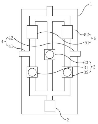
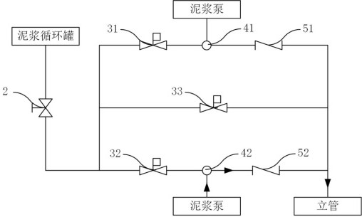
[0049] combined with figure 1 and 2 , this embodiment provides a high-pressure mud manifold, including a drill floor valve group 03, the drill floor valve group 03 is respectively connected to a mud pump 02 and a standpipe 04, the mud pump 02 is connected to a mud circulation tank 01, and the The riser 04 is connected to the drill bit 05, and the drill floor valve group 03 includes a skid seat 1, and the skid seat 1 is provided with a flat gate valve 2, an electric valve group 3, a mud pump interface group 4, a one-way valve group 5 and Connecting pipelines, the flat gate valve 2 is arranged between the mud circulation tank 01 and the electric valve group 3, and the mud pump interface group 4 is arranged between the electric valve group 3 and the one-way valve group 5 Between, the one-way valve group 5 is connected to the standpipe 04 .

[0050] In the above technical solution, the mud circulation tank 01 contains drilling mud, and the mud pump 02 pumps the mud in the mud ci...

Embodiment 2

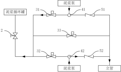
[0054] combined with Figures 2 to 6 , on the basis of Embodiment 1, this embodiment provides a high-pressure mud manifold with multiple operating modes, the high-pressure mud manifold includes a single-pump operating mode, a double-pump operating mode and a protection mode, the single In the pump operation mode, one mud pump 02 is enabled, and one mud pipeline is defined by the drill floor valve group 03. In the dual-pump operation mode, two mud pumps 02 are enabled, and two mud pipelines are defined by the drill floor valve group 03. In the protection mode, the mud pressure relief pipeline is opened through the drill floor valve group 03 .

[0055] The electric valve group 3 includes a first electric valve 31, a second electric valve 32 and a third electric valve 33, the mud pump interface group 4 includes a first mud pump interface 41 and a second mud pump interface 42, the single The one-way valve group 5 includes a first one-way valve 51 and a second one-way valve 52, th...

Embodiment 3

[0060] combined with Figures 7 to 12 , the present embodiment provides a structure of a high-pressure check valve with a shock-absorbing effect, the first check valve 51 and the second check valve 52 have the same structure, including a hollow housing 100, and the housing 100 has two A mud inlet 200 and a mud outlet 300 are respectively provided at the ends of the housing 100. A valve seat 400 and a valve core 500 are arranged in sequence along the mud flow direction in the housing 100. The valve core 500 is connected to one end of the spring 600, and the other end of the spring 600 One end is fixed on the housing 100, the valve core 500 is provided with a cylindrical cavity 520 through which the mud flows into the mud outlet 300, the cavity 520 includes an inlet section 521, a reducing The inner diameters of the shock section 522 and the outlet section 523, the inlet section 521 and the shock absorption section 522 are consistent.

[0061] Among the above technical solution...


PUM


Abstract

The present invention relates to the technical field of petroleum drilling, and in particular to a high-pressure mud manifold and a method for using the same. The high-pressure mud manifold includes a drill floor valve group, and the drill floor valve group is respectively connected to a mud pump and a standpipe. The mud pump Connected to the mud circulation tank, the riser is connected to the drill bit, and the drill floor valve group includes a skid seat, and the skid seat is equipped with a flat gate valve, an electric valve group, a mud pump interface group, a one-way valve group and a connecting pipe Road, the flat gate valve is arranged between the mud circulation tank and the electric valve group, the mud pump interface group is arranged between the electric valve group and the one-way valve group, and the one-way valve Set connects the risers. The invention has good damping effect, simple and convenient operation and control, reduces the labor intensity of on-site workers, improves the safety factor, and satisfies the explosion-proof and safety requirements on the drilling site.

Description

technical field [0001] The invention relates to the technical field of petroleum drilling, in particular to a high-pressure mud manifold and a method for using the same. Background technique [0002] The high-pressure mud manifold is the necessary equipment to increase the drilling speed in high-pressure jet drilling. It collects the mud discharged from the mud pump and uses the control of the valve group to input the high-pressure mud liquid into the inner cavity of the drill pipe and eject it from the drill pipe bit to generate high pressure. Mud torrents realize high-pressure jet drilling, the drilling speed is greatly improved, and the drilling cost is reduced. At present, although the high-pressure mud circulation manifold is guaranteed in terms of pressure bearing capacity, the design is often not humanized enough, and there are problems such as inconvenient use and large vibration. In addition, most of the valves in the valve group are manual valves, requiring worker...

Claims


Application Information

Patent Timeline
Patent Type & Authority Patents(China)
IPC IPC(8): E21B21/00E21B21/10
CPCE21B21/00E21B21/10E21B2200/04
Inventor 李晓明李联中江正清赵波张国华李振华
Owner DONGYING XIN HUALIAN PETROLEUM MACHINERY
Why Eureka
Try Eureka