A plugging and sealing device with crack guiding function during static crushing

A technology of static crushing and sealing device, applied in blasting and other directions, can solve the problem of high control cost, achieve the effect of saving drilling cost, simple assembly and expanding hole spacing

Active Publication Date: 2021-06-22
HARBIN INST OF TECH
View PDF0 Cites 0 Cited by
  • Summary
  • Abstract
  • Description
  • Claims
  • Application Information

AI Technical Summary

Problems solved by technology

[0004] In order to solve the problem of high cost of nozzle hole and crack direction control in the existing static crushing process, the present invention proposes a plugging and sealing device with crack guiding function in the static crushing process

Method used


Image

  • A plugging and sealing device with crack guiding function during static crushing
  • A plugging and sealing device with crack guiding function during static crushing
  • A plugging and sealing device with crack guiding function during static crushing

Examples


specific Embodiment approach 1

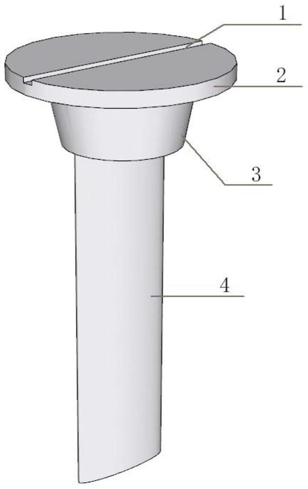
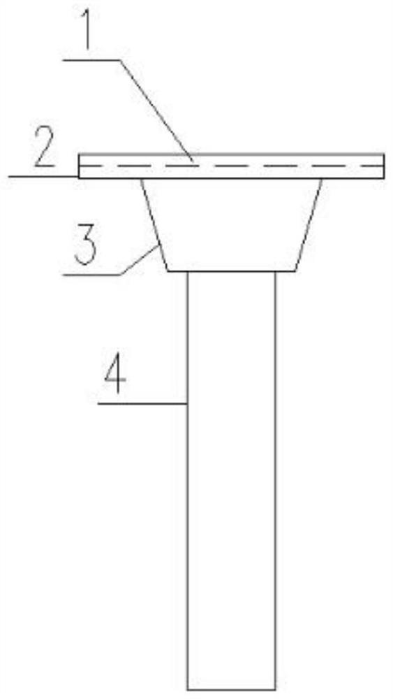
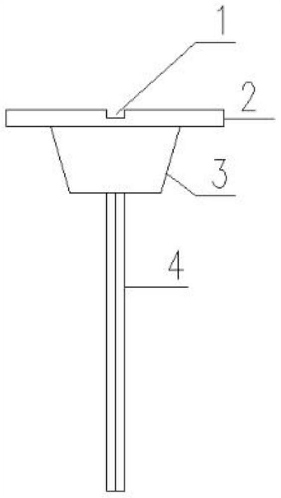
[0015] Specific Embodiment 1: This embodiment is a plugging and sealing device with crack guiding function in the static crushing process, which includes a plugging member and a fixing member; The hole part and the crack guide part; the direction indicating part is composed of a groove 1 and a round steel sheet 2, the closed plugging part is a short steel column 3, and the crack guide part is an arc-shaped steel plate 4; the fixing The component is composed of a top steel plate 5, a nut 6, a screw rod 7 and a bottom steel plate 8; the top steel plate 5 and the bottom steel plate 8 are arranged in parallel and symmetrically, and the four corners of the top steel plate 5 and the bottom steel plate 8 are provided with holes, and the top steel plate 5 and the bottom The four corners of the steel plate 8 are respectively connected and fixed by the screw rod 7, and the two ends of the screw rod 7 are locked by the nut 6; the short steel column 3 is arranged on the upper end of the cu...

specific Embodiment approach 2

[0017] Specific embodiment two: the difference between this embodiment and specific embodiment one is: the use method of the plugging and sealing device with crack guiding function in the static crushing process is specifically carried out according to the following steps: first drill the blast hole on the concrete member 9, Stir the static breaking agent evenly and fill it into the blast hole, then insert the plugging member into the blast hole, the short steel column 3 seals the blast hole tightly, and then rotate the round steel sheet 2 to ensure that the direction of the groove 1 is in line with the expected cracking The direction is the same, and finally the top steel plate 5 is placed on the upper surface of the sealing member, the bottom steel plate 8 is placed on the lower surface of the concrete member 9, and the four corners of the top steel plate 5 and the bottom steel plate 8 are respectively connected and fixed by the screw rod 7, and the The two ends are locked by...

specific Embodiment approach 3

[0019] Embodiment 3: This embodiment differs from Embodiment 1 or Embodiment 2 in that: the short steel column 3 is a rounded truss structure. Others are the same as those in Embodiment 1 or 2.


PUM


Abstract

The invention relates to a hole blocking and sealing device with a crack guiding function during static crushing. The invention belongs to the technical field of static crushing and dismantling concrete, and in particular relates to a hole blocking sealing device with a crack guiding function in the static crushing process. The invention statically crushes the punching problem in the process of removing the concrete structure and realizes a certain degree of crack control. It includes a blocking member and a fixing member; the blocking member is an integral structure, which is composed of a direction indicating part, a closing plugging part and a crack guiding part; the direction indicating part is composed of a groove and a round steel sheet, and the The closed hole plugging part is a short steel column, the crack guiding part is a curved steel plate; the fixing member is composed of a top steel plate, a nut, a screw rod and a bottom steel plate. The invention is used for plugging sealing and crack guiding in static crushing process.

Description

technical field [0001] The invention belongs to the technical field of static crushing and demolition of concrete, in particular to a hole plugging and sealing device with crack guiding function in the static crushing process. Background technique [0002] Since the static breaking agent mainly undergoes an exothermic reaction, when this method is actually applied, the reaction is carried out in a blast hole with a narrow space and poor thermal conductivity. With the hydration of the breaking agent, a large amount of hydration heat generated in a short time It cannot be exported through the surrounding medium in time, resulting in the rapid gasification of the water in the static breaking agent slurry, resulting in a large steam pressure. When the generated steam pressure is greater than the cohesive force between the static breaking agent slurry and the blasthole wall, the static breaking agent will punch holes. [0003] Experiments have shown that plain concrete single-ho...

Claims


Application Information

Patent Timeline
Patent Type & Authority Patents(China)
IPC IPC(8): F42D1/18F42D3/00
CPCF42D1/18F42D3/00
Inventor 李瑞森张弛郑文忠王英徐笠博
Owner HARBIN INST OF TECH
Why Eureka
Try Eureka