
Intelligent sensor for measuring high current

A smart sensor and high current technology, applied in the direction of measuring electricity, measuring electrical variables, parts of electrical measuring instruments, etc., can solve the problem of low accuracy

Active Publication Date: 2013-02-27
INST OF ELECTRICAL ENG CHINESE ACAD OF SCI
View PDF4 Cites 27 Cited by
  • Summary
  • Abstract
  • Description
  • Claims
  • Application Information

AI Technical Summary

Problems solved by technology

The measurement method of the shunt needs to be isolated, and the accuracy is not high without temperature compensation

Method used


Image

  • Intelligent sensor for measuring high current
  • Intelligent sensor for measuring high current
  • Intelligent sensor for measuring high current

Examples


Embodiment Construction

[0017] The present invention will be further described below in conjunction with the drawings and specific embodiments.

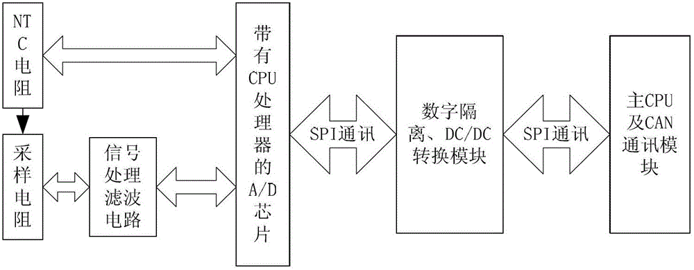
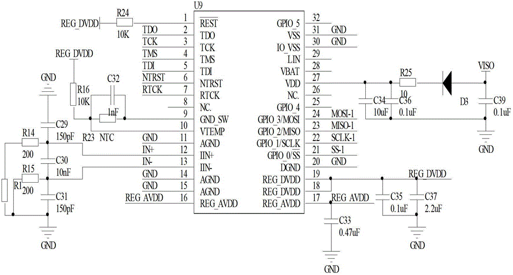
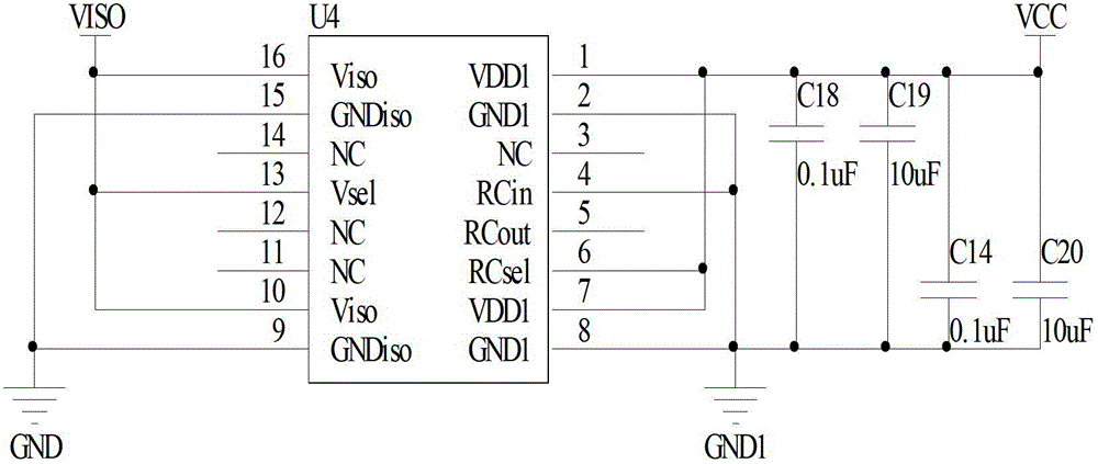
[0018] figure 1 It is a block diagram of the present invention. The large current passes through the sampling resistor R1 to generate a voltage proportional to the magnitude of the current. After this voltage passes through the signal processing filter circuit, it enters the current measurement channel with the CPU processor A / D chip U9. The NTC thermistor is fixed on the surface of the sampling resistor to measure the temperature signal on the surface of the high-power sampling resistor R1, and the temperature signal on the surface of the high-power sampling resistor R1 enters the temperature measurement channel with the CPU processor A / D chip U9. The A / D chip U9 with CPU processor will measure the current value and communicate with the outside through the SPI communication interface. After the digital isolation and DC / DC conversion module isolates the SPI d...


PUM


Abstract

Provided is an intelligent sensor for measuring high current. A large-power sampling resistor (R1) of the intelligent sensor converts current signals into voltage signals. Converted voltage signals are processed and filtered through a signal processing filter circuit and fed to an AD chip (U9). A negative temperature coefficient (NTC) thermal resistor (R23) is adopted by a temperature measurement module to measure the temperature of the large-power sampling resistor so as to be used for temperature compensation for the large-power sampling resistor. The AD chip converts output voltage of the measuring signal processing filter circuit and the temperature value of the NTC thermal resistor into digital signals, digital filtering processing is performed, and digital signals of voltage and the temperature are sent to an external main central processing unit (CPU) through a serial peripheral interface (SPI) communication interface isolated through an optocoupler. Isolation of the SPI communication digital signals is achieved through a digital isolation and direct current (DC) / DC conversion module, and the digital isolation and DC / DC conversion module supplies power to the signal processing filter circuit, the temperature measurement module and an analog to digital (A / D) conversion chip with a CPU processor. The main CPU and a controller area network (CAN) communication module receive external instructions and send digital signals of current measurement values.

Description

Technical field [0001] The invention relates to a sensor for measuring high voltage and large current. Background technique [0002] In the field of industrial technology and electric vehicles, it is often necessary to measure large currents, and the current dynamic range is often -1000A~+1000A. At present, the commonly used method is to use Hall sensors and shunts to measure, and the analog signal needs to be further processed during use. Patent CN1442696 "Battery Current Measurement System for Electric Vehicles" uses a Hall sensor to convert the analog voltage output by the Hall into a PWM waveform output. The shortcoming of patent CN1442696 is that the linearity of the Hall sensor measurement will change with time, it is difficult to achieve long-term high-precision measurement, and the PWM waveform needs to be processed during use. The patent CN1193386 "shunt component for current measurement" uses a shunt to measure current. Patent CN1397963 "Current measuring device and ...

Claims


Application Information

Patent Timeline
Patent Type & Authority Applications(China)
IPC IPC(8): G01R19/25G01R1/44G01R15/22G01R1/30
Inventor 徐冬平王丽芳王立业
Owner INST OF ELECTRICAL ENG CHINESE ACAD OF SCI
Learn More