
A comprehensive stiffness test device for armature components of servo valves

A test device and servo valve technology, which is applied in the field of servo valves, can solve the problems of low test efficiency, many error influencing factors, and difficult operation, and achieve the effects of good test data consistency, accurate loading, and simple test process

Active Publication Date: 2020-09-01
SHANGHAI AEROSPACE CONTROL TECH INST
View PDF4 Cites 0 Cited by
  • Summary
  • Abstract
  • Description
  • Claims
  • Application Information

AI Technical Summary

Problems solved by technology

[0003] (1) Knocking method: The knocking method is generally realized by knocking one end of the armature assembly. The comprehensive stiffness of the armature assembly measured by this method has defects such as discrete data, large errors, and poor consistency. In addition, this measurement The method is disturbed by many factors and cannot achieve high-precision measurement
[0004] (2) Resonance method: The resonance method is tested by inputting voltage or current to the torque motor, through which the comprehensive stiffness of the armature assembly is indirectly reversed, and the test process is complicated by this method, which requires electrical signals and installation components The method of torque motor components is used, the test efficiency is low, and rapid quantitative detection cannot be achieved
[0005] The above two working methods are difficult to operate in practical applications, the test process is complicated, and there are many error influencing factors, which are difficult to meet the high-precision and high-efficiency test requirements of the servo valve armature assembly.

Method used


Image

  • A comprehensive stiffness test device for armature components of servo valves
  • A comprehensive stiffness test device for armature components of servo valves

Examples


Embodiment Construction

[0019] Hereinafter, in conjunction with the accompanying drawings, a preferred specific embodiment is described in detail to further illustrate the present invention.

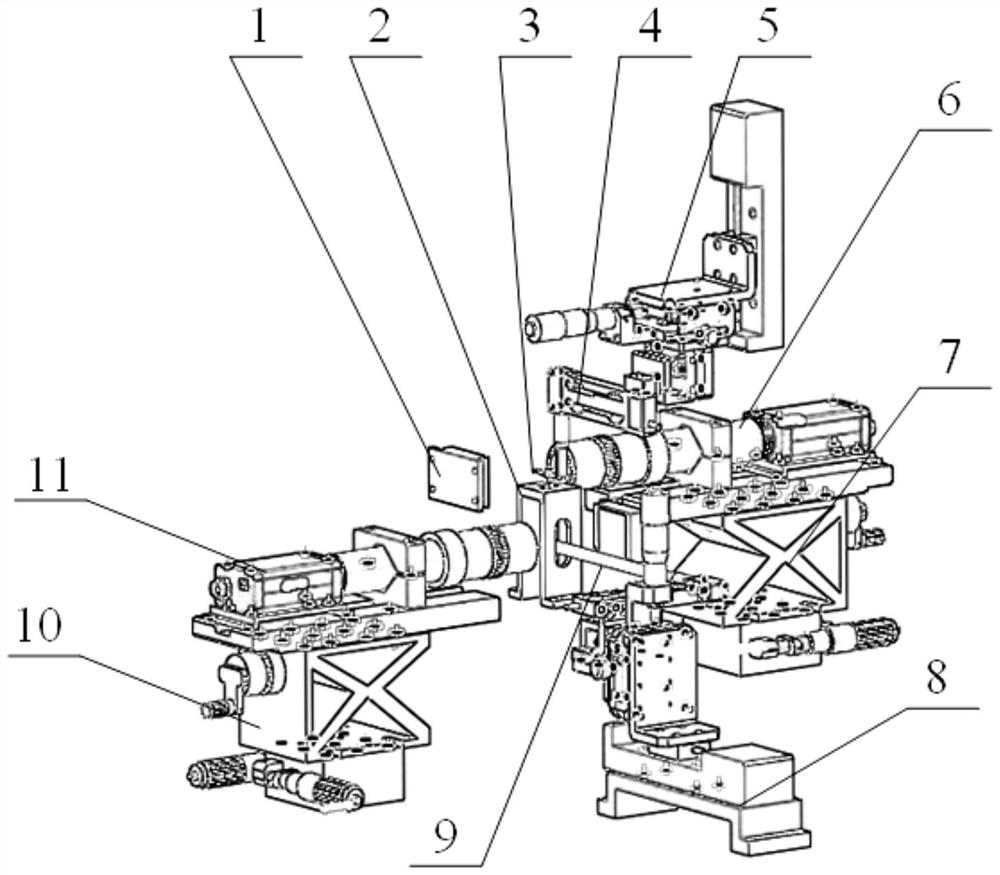
[0020] Such as figure 1 As shown, the present embodiment provides a servo valve armature assembly comprehensive rigidity test device, which is used to simulate the servo valve to test the armature assembly under normal working conditions. The test device includes: armature assembly positioning fixture 2, armature Component force loading equipment 4, armature component force loading adjustment equipment 5, armature displacement detection equipment 6, armature displacement detection and adjustment equipment 7, baffle displacement detection equipment 10, baffle displacement detection and adjustment equipment 11, feedback rod displacement loading equipment 8, feedback Rod displacement loading adjustment device 9, feedback rod displacement detection device 1, and the armature assembly force loading device 4, armature as...


PUM


Abstract

The invention discloses an integrated stiffness testing device for a servo valve armature component. The device comprises an armature component positioning fixture provided with an armature componentto be tested, armature component force loading equipment, armature displacement detection equipment, baffle displacement detection equipment, feedback rod displacement loading equipment and feedback rod displacement detection equipment, wherein the armature component force loading equipment applies a force load to one end of the armature of the armature component; the armature displacement detection equipment is used for carrying out displacement detection on the other end of the armature of the armature component to obtain the displacement data of the armature; the baffle displacement detection equipment is used for carrying out displacement detection on the baffle of the armature component to obtain the displacement data of the baffle; the feedback rod displacement loading equipment is used for applying the force load to the upper end of the feedback rod; and the feedback rod displacement detection equipment is used for carrying out displacement detection on the bulb of the lower endof the feedback rod to obtain the displacement data of the bulb. The device has the advantages of simple testing process and high testing data accuracy.

Description

Technical field [0001] The invention relates to the technical field of servo valves, in particular to a comprehensive rigidity test device for a servo valve armature assembly. Background technique [0002] In recent years, the application and development of electro-hydraulic servo control technology is considered to be one of the important indicators for measuring a country’s industrial manufacturing level and modern industrial development. It is used in precision machine tools, engineering machinery, metallurgy, mining, petrochemical, electrochemical, shipbuilding and military industries. It has a wide range of applications in host products. The electro-hydraulic servo valve is a key component in the electro-hydraulic servo control system, and the armature assembly is the most critical moving component in the electro-hydraulic servo valve. Its performance directly restricts the performance of the electro-hydraulic servo valve and even the entire electro-hydraulic servo system. ...

Claims


Application Information

Patent Timeline
Patent Type & Authority Patents(China)
IPC IPC(8): G01M5/00
CPCG01M5/0075
Inventor 江金林王晓露鲜亚平郭加利王玥
Owner SHANGHAI AEROSPACE CONTROL TECH INST
Learn More