Near-field wide-view-angle beam forming method of real-time three-dimensional imaging sonar

An imaging sonar, real-time three-dimensional technology, applied in the direction of sound wave reradiation, radio wave measurement system, instrument, etc., can solve the problems of narrow detection area and low near-field focusing accuracy, expand the viewing angle, and improve near-field focusing accuracy , the effect of high near-field focusing accuracy

Active Publication Date: 2019-04-05
HUAZHONG UNIV OF SCI & TECH +1
View PDF7 Cites 7 Cited by
  • Summary
  • Abstract
  • Description
  • Claims
  • Application Information

AI Technical Summary

Problems solved by technology

[0005] Aiming at the above defects or improvement needs of the prior art, the present invention provides a near-field wide-angle beamforming method for real-time three-dimensional imaging sonar, wherein based on the Fresnel approximation time delay, the Fresnel approximation time delay is calculated by us...

Method used


Image

  • Near-field wide-view-angle beam forming method of real-time three-dimensional imaging sonar
  • Near-field wide-view-angle beam forming method of real-time three-dimensional imaging sonar
  • Near-field wide-view-angle beam forming method of real-time three-dimensional imaging sonar

Examples


Embodiment Construction

[0037] In order to make the object, technical solution and advantages of the present invention clearer, the present invention will be further described in detail below in conjunction with the accompanying drawings and embodiments. It should be understood that the specific embodiments described here are only used to explain the present invention, not to limit the present invention. In addition, the technical features involved in the various embodiments of the present invention described below can be combined with each other as long as they do not constitute a conflict with each other.

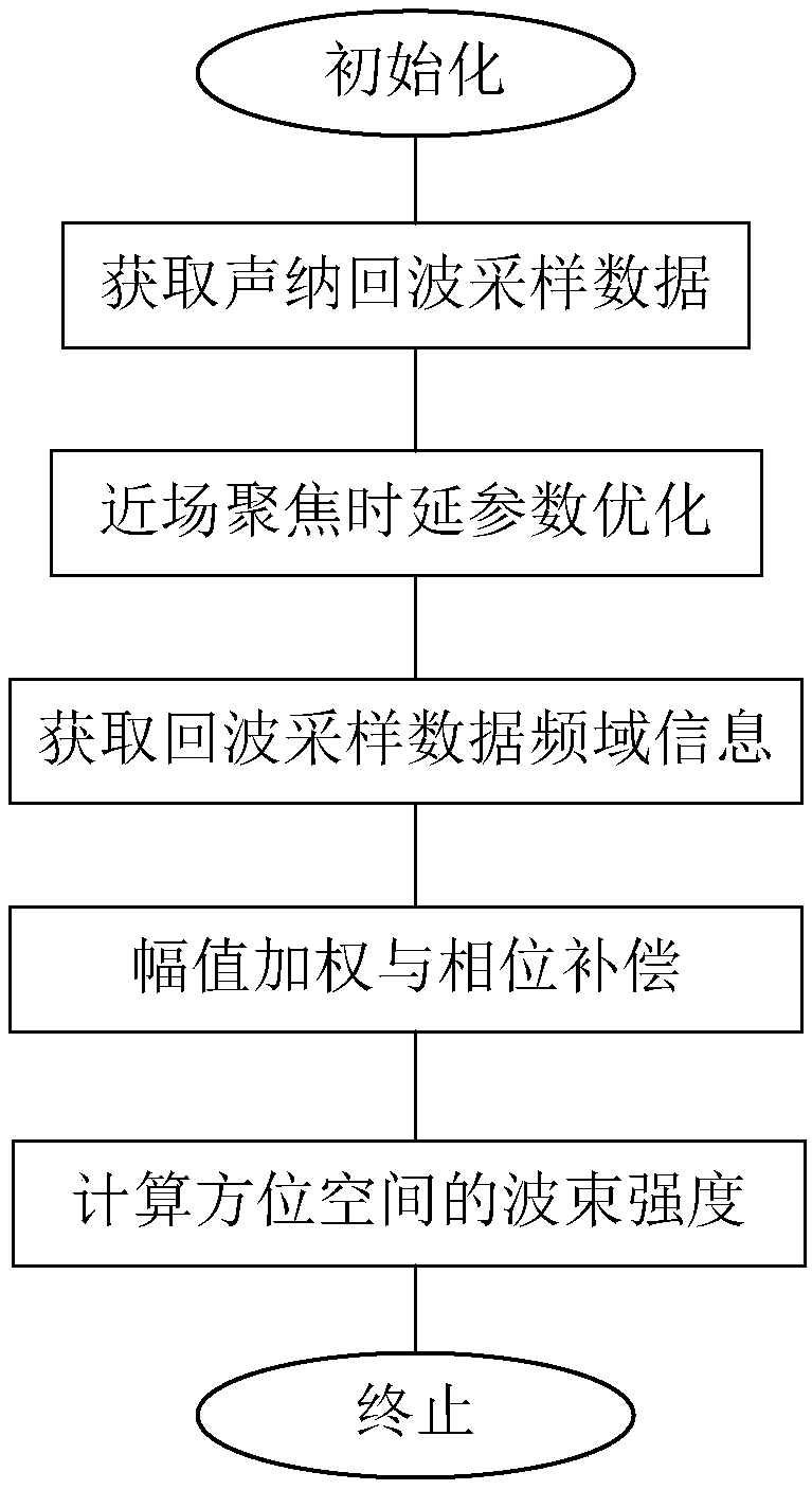
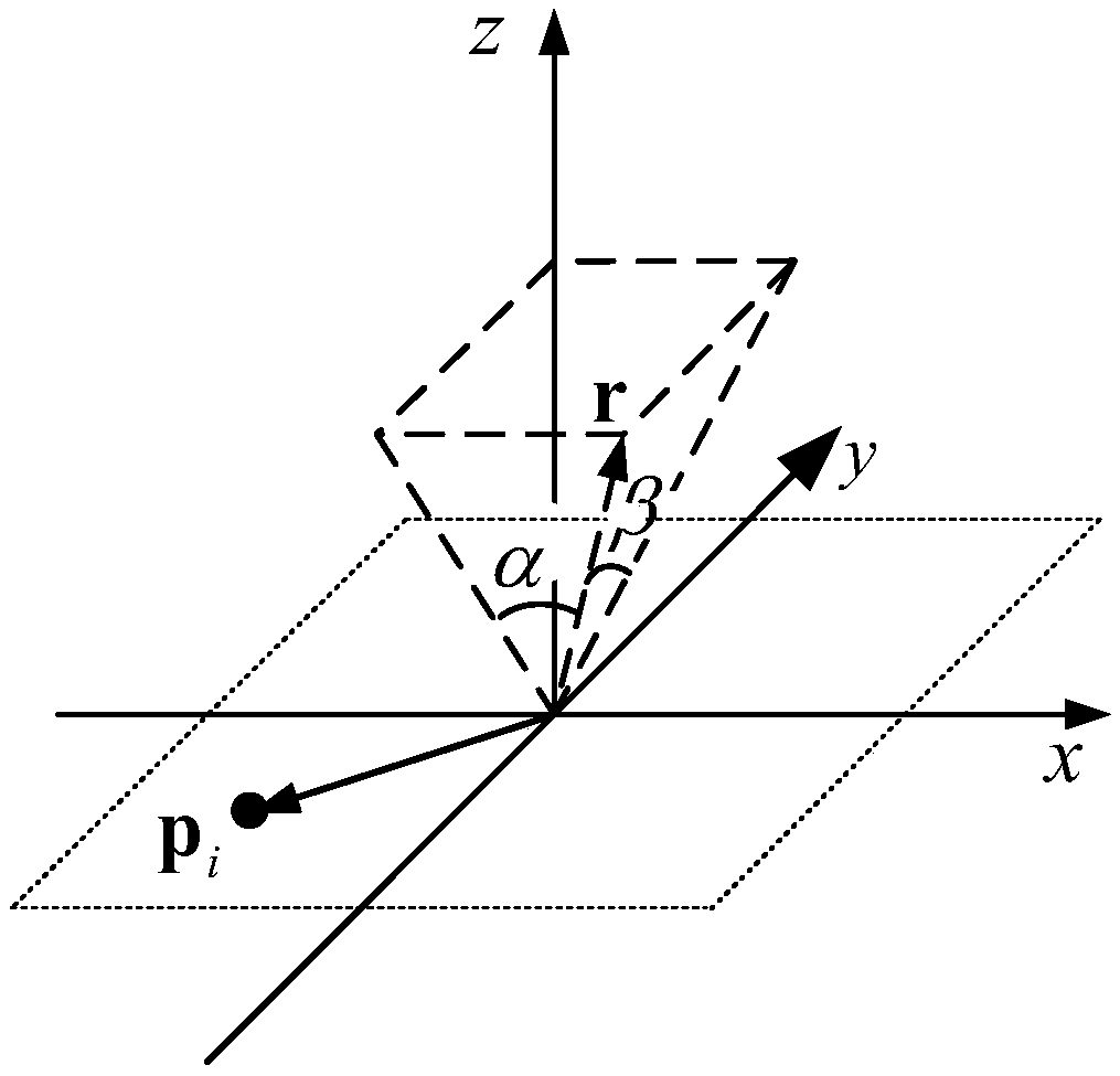
[0038] like figure 1 , figure 2 As shown, the present invention proposes a near-field wide viewing angle beamforming method of a real-time three-dimensional imaging sonar, which is characterized in that the method comprises the following steps:

[0039] S1 obtains the echo sampling data matrix S of the sonar system, the sonar system is a transducer array composed of I transducer array element...


PUM


Abstract

The invention belongs to the technical field of three-dimensional sonar, and discloses a near-field wide-view-angle beam forming method of real-time three-dimensional imaging sonar. The near-field wide-view-angle beam forming method comprises the following steps that an echo sampling data matrix S of a sonar system is obtained; a time delay weighting coefficient k1 of a focusing target point inside a Fresnel time delay area and a time delay weighting coefficient k2 of the focusing target point outside the Fresnel time delay area are calculated; echo sampling data are subjected to L-point discrete Fourier transformation, and thus an echo signal S(l) is obtained; the echo signal S(l) is subjected to amplitude weighting and phase compensation, and thus a compensated echo signal tilde{S(l)} isobtained; .and the compensated echo signal tilde{S(l)} is subjected to fast Fourier transformation, an expression of the spatial beam intensity is obtained, and the spatial beam intensity is calculated. As for the situations that the focusing target point is located outside the Fresnel time delay area and located in a set imaging view angle range, the time delay weighting coefficients are optimized through a least squares method, under the premise of ensuring near-field beam forming calculation efficiency, near-field focusing accuracy can be effectively improved, and the view angle of near-field imaging is expanded.

Description

technical field [0001] The invention belongs to the technical field of three-dimensional sonar, and more specifically relates to a near-field wide-angle beam forming method of a real-time three-dimensional imaging sonar. Background technique [0002] Real-time 3D imaging sonar is a 3D acoustic imaging device developed in recent years to meet the growing demand for 3D detection of underwater targets. This type of 3D sonar has good imaging resolution and real-time imaging performance. There are a wide range of application requirements in engineering operations, marine scientific research, and national defense and military fields. Its basic imaging principle is: the system uses a narrow-band acoustic pulse to transmit the entire observation scene, uses phased array technology to simultaneously generate tens of thousands of real-time beam intensity signals, and obtains a three-dimensional scene image through real-time signal processing. The core technology of the imaging system...

Claims


Application Information

Patent Timeline
IPC IPC(8): G01S15/88G01S7/52
CPCG01S7/52036G01S15/88
Inventor 罗再磊韩斌陈学东孟路稳赵德鑫
Owner HUAZHONG UNIV OF SCI & TECH
Why Eureka
Try Eureka