
Fast beam smoothing method based on beam dynamic interference patterns in inertially confinement fusion device

A technology of inertial confinement fusion and dynamic interference, which is applied in the field of fast beam smoothing based on beam dynamic interference pattern, can solve the problems of high cost and difficult realization of pump light, and can reduce focal spot, improve irradiation uniformity, avoid The effect of intensity modulation

Active Publication Date: 2019-04-05
SICHUAN UNIV
View PDF16 Cites 3 Cited by
  • Summary
  • Abstract
  • Description
  • Claims
  • Application Information

AI Technical Summary

Problems solved by technology

However, the pump light required by the radial beam smoothing technology is difficult to achieve and the cost is high

Method used


Image

  • Fast beam smoothing method based on beam dynamic interference patterns in inertially confinement fusion device
  • Fast beam smoothing method based on beam dynamic interference patterns in inertially confinement fusion device
  • Fast beam smoothing method based on beam dynamic interference patterns in inertially confinement fusion device

Examples


Embodiment 1

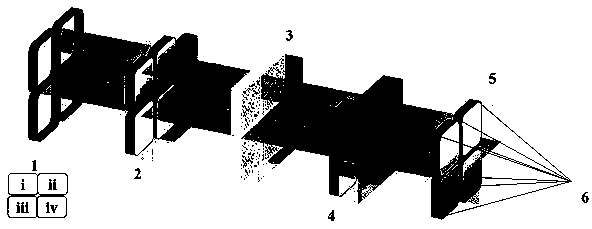
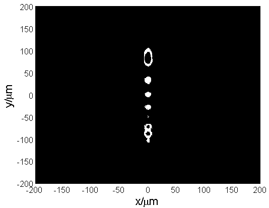
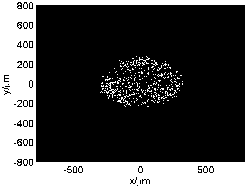
[0037]The conjugated phase plate used in this embodiment is a tilted phase plate with a phase PV (peak-to-valley) value of 2λ (λ=351nm) and an aperture of 372mm×372mm. To achieve a comparable effect to 2D-SSD, the tilted phase plates of sub-beams i and ii are tilted along the x direction, while the tilted phase plates of sub-beams iii and iv are tilted along the y direction. The working wavelength of each sub-beam in the laser beam is λ i =λ iii =351nm,λ ii =λ iv =351.1nm, the polarization states of sub-beam i and sub-beam ii are x-line polarization, and the polarization states of sub-beam iii and sub-beam iv are both y-line polarization. The integration time is 10ps.

[0038] Figure 2 shows the phase distribution of the conjugated phase plate, which can be but not limited to oblique phase, cylindrical phase, spherical phase and helical phase. This embodiment adopts the oblique phase in (a).

[0039] For the convenience of comparison, the fast beam smoothing method of Exa...

Embodiment 2

[0056] The conjugated phase plate used in this embodiment is a cylindrical phase plate with a phase PV (peak-to-valley) value of 2λ (λ=351nm) and an aperture of 372mm×372mm. In order to achieve a comparable effect to 2D-SSD, the cylindrical phase plates of sub-beams i and ii are aligned along the x direction, while those of sub-beams iii and iv are aligned along the y direction. The working wavelength of each sub-beam in the laser beam is λ i =λ iii =351nm,λ ii =λ iv =351.2nm, the polarization states of sub-beam i and sub-beam ii are x-line polarization, and the polarization states of sub-beam iii and sub-beam iv are both y-line polarization. The integration time is 5ps. The other operation steps and operation process are the same as in Embodiment 1, and the same effect of improving the uniformity of the far-field focal spot of the laser beam as in Embodiment 1 can be obtained.

[0057] Use formulas (4) and (5) to calculate the luminous flux contrast ratio of the focal sp...


PUM


Abstract

The invention relates to a fast beam smoothing method based on beam dynamic interference patterns in an inertially confinement fusion device. The method comprises the steps that in laser bunched beamof the laser-driven inertially confinement fusion device, the beam is divided into sub-beam pairs which are combined in pairs, all the sub-beam pairs pass through the same continuous phase plate and polarization control plate and are different in working wavelength, a pair of conjugate or complementary phase plates are correspondingly inserted into the sub-beam pairs, and fast smoothing of far-field focal spots of a laser beam is realized through far-field dynamic interference patterns between the sub-beam pairs, so that the uniformity of the focal spot is improved in a short integration time.

Description

technical field [0001] The invention relates to a beam smoothing technology in a laser-driven inertial confinement fusion (ICF) device, in particular to a fast beam smoothing method based on a beam dynamic interference pattern in a laser-driven inertial confinement fusion device. Background technique [0002] In the laser-driven inertial confinement fusion (ICF) device, various spatial and time domain beam smoothing technologies are widely used to control the uniformity of the far-field focal spot of the laser beam, so as to meet the requirements of physical experiments. The device can precisely control the light field distribution on the target surface. In the existing spatial beam smoothing technology, the continuous phase plate is often used to control the envelope and uniformity of the far-field focal spot of the laser beam. plaque structure. This type of speckle structure will lead to the generation of various nonlinear instability effects during the interaction betwe...

Claims


Application Information

Patent Timeline
IPC IPC(8): G02B27/48G02B27/28
CPCG02B27/286G02B27/48
Inventor 钟哲强张彬孙年春
Owner SICHUAN UNIV
Learn More