Solar simulator

a solar simulator and simulator technology, applied in the field of optical systems, can solve the problems of difficult maintenance, difficult to efficiently reduce the non-uniform and difficult to properly control or adjust the distribution of ray radiation, so as to achieve better uniformity of irradiance on the test plane

Active Publication Date: 2015-02-24
IND TECH RES INST
View PDF28 Cites 1 Cited by
  • Summary
  • Abstract
  • Description
  • Claims
  • Application Information

AI Technical Summary

Benefits of technology

[0008]The disclosure is directed to a solar simulator which can achieve the better uniformity of irradiance on the test plane.
[0009]The disclosure is directed to a solar simulator which can achieve the better uniformity of irradiance on the test plane under a plurality of light sources.
[0012]In view of the above, a light conduit array consisting of a plurality of light conduits and one or more light source is configured above the light conduit array according to the disclosure. Under the configuration of the light conduit array, the ray radiation emitted from the light source may have the better uniformity of irradiance on the test plane by the effect of the plurality of light conduits. In addition, the solar simulator can be configured with a plurality of light sources for accomplishing even ray radiation of large area exposure.

Problems solved by technology

However, owing that the ray radiation from the plurality of lights can be overlapped and interfered mutually and the scattering light is difficult to be eliminated, the distribution of the ray radiation is complicate and difficult to properly controlled or adjusted by the prior art.
Such methods of locally adjusting the relative positions of the components may have influence on the light intensity of other regions where the relative positions of the components are not changed, so that the ray radiation distribution of the exposure area must be modulated again, which is time-consuming, difficult to maintain, and failing to efficiently reduce the non-uniformity of irradiance on the test plane.
By using the solar simulator to perform the test on the photovoltaic module, the measurement error is not easily to be reduced.

Method used


Image

  • Solar simulator
  • Solar simulator
  • Solar simulator

Examples


first embodiment

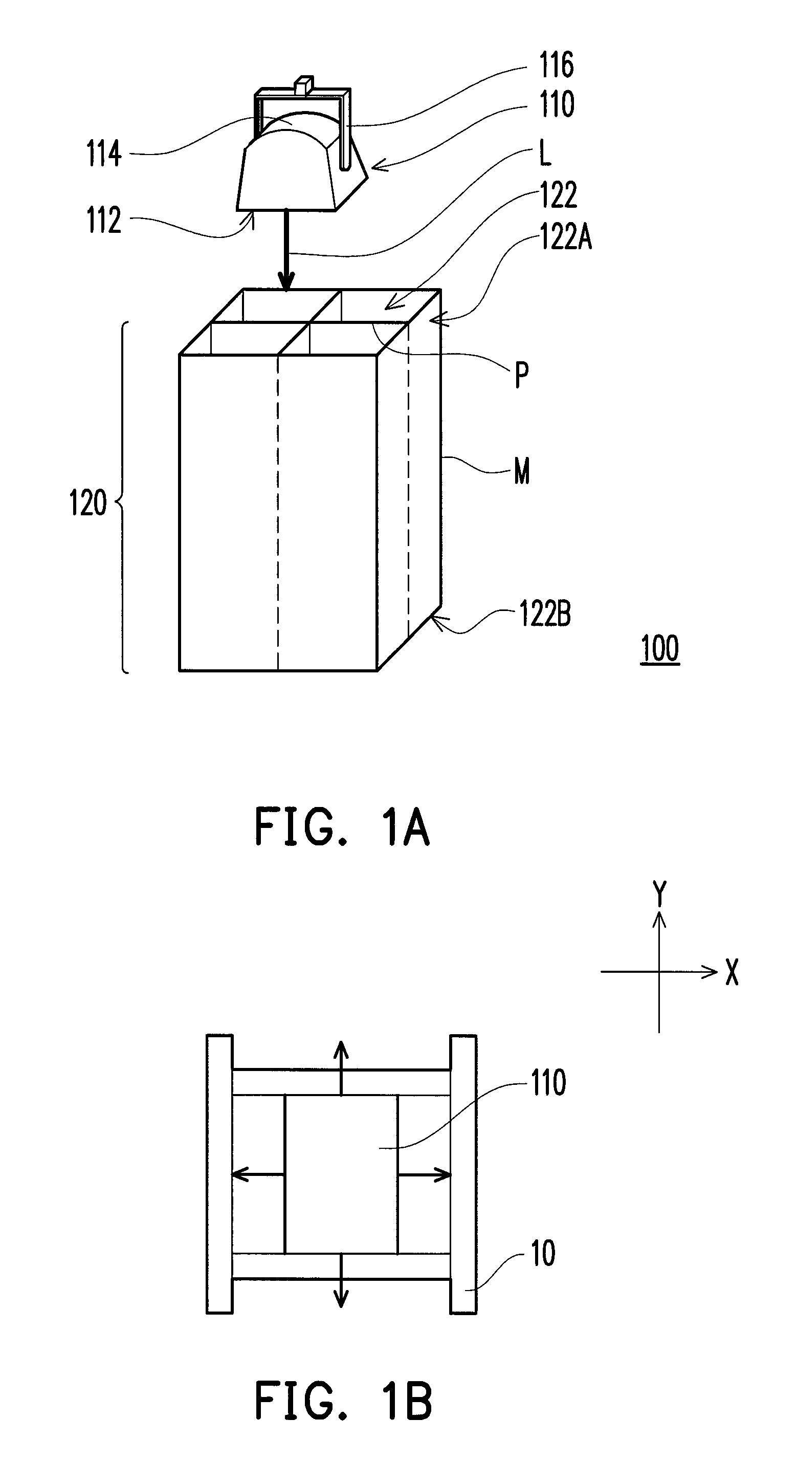
[0022]FIG. 1A is a schematic view of a solar simulator according to the present disclosure. Referring to FIG. 1A, a solar simulator 100 includes a light source 110 and a light conduit array 120. The light source 110 has a light emitting surface 112 and is used for emitting a beam of ray radiation L. The light conduit array 120 includes a plurality of light conduits 122 closely adjacent to one another and is configured in a light path of the ray radiation L. Each of the light conduits 122 has an inner reflecting surface P reflecting the ray radiation therein, a light input side 122A, and a light output side 122B opposite to the light input side 122A. The ray radiation L enters the light conduits 122 through the light input side 122A and emitting from the light output side 122B so as to provide the required simulated solar light. That is to say, the light input side 122A are relatively closer to the light emitting surface 112 and the light output side 122B are relatively farther from ...

third embodiment

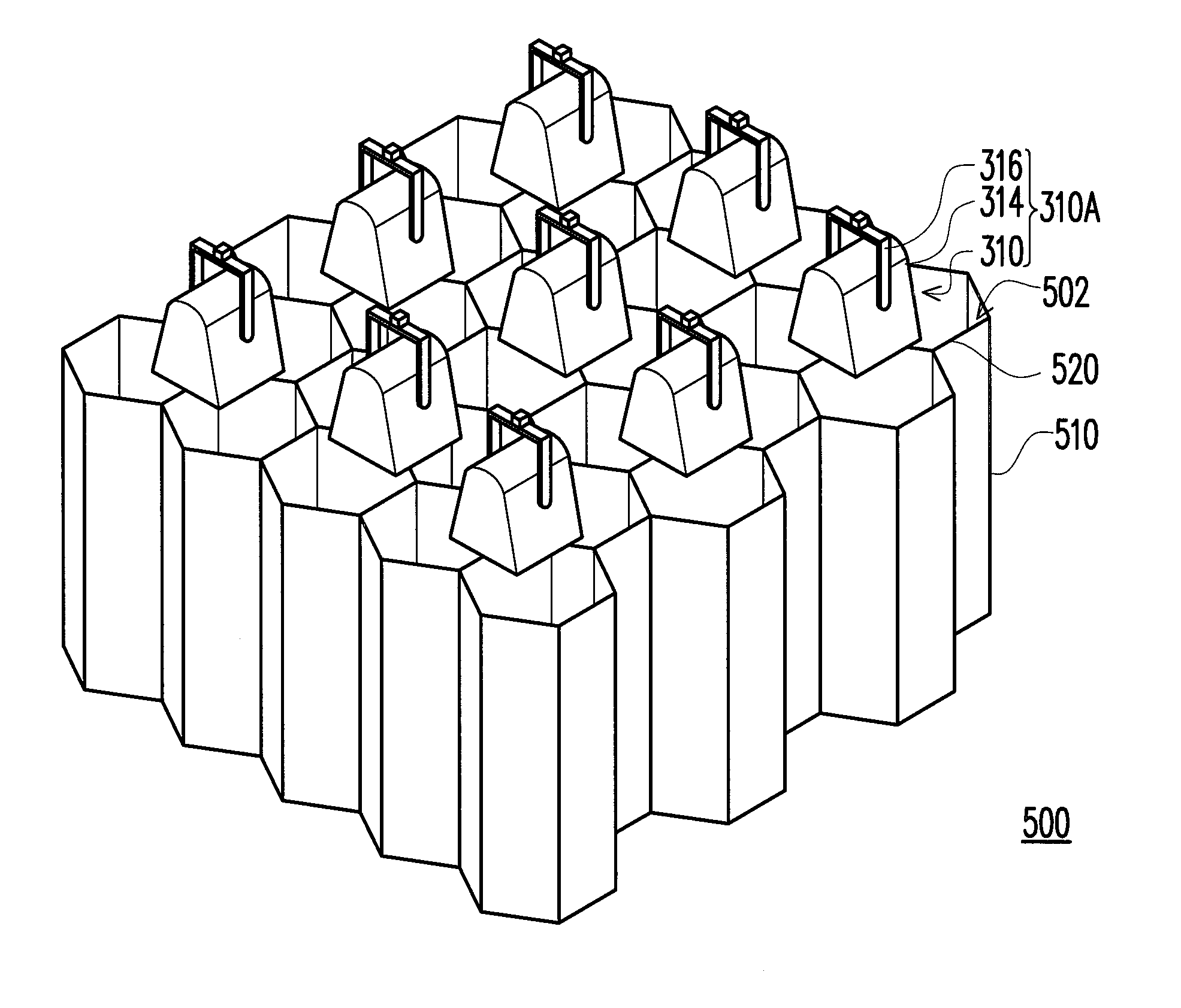
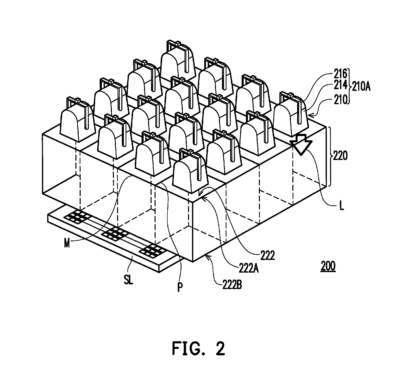
[0035]FIG. 3A is a schematic view of a solar simulator according to the present disclosure. Referring to FIG. 3A, a solar simulator 300 including a plurality of light sources 310 and a light conduit array 320, wherein each of the light light sources 310 is used for emitting a ray radiation L from the light emitting surface 312 and the light conduit array 320 includes a plurality of light conduits 322. In specific, the light sources 310 construct a light source array 310A, for example. Each of the light conduit 322 configured in the light path of the ray radiation L has an inner reflecting surface P reflecting the ray radiation L, a light input side 322A, and a light output side 322B. The light input side 322A are relatively closer to the light emitting surface 312 and the light output side 322B are relatively farther from the light emitting surface 312 such that the light emitting surface 312 faces the light input side 322A. In the present embodiment, the light source 310 can includ...

second embodiment

[0036]Specifically, the difference between the present embodiment and the second embodiment mainly lies in that each of the light sources 310 in the present embodiment corresponds to a plurality of the light conduits 322. Each light source 310 in the present embodiment corresponds, for example, to four light conduits 322 so that the number of the light sources 310 is less than that of the light conduits 322. Furthermore, each light source 310 can be located corresponding to the center of the area defined by four closely adjacent light conduits 322, i.e. the light conduit array 320 parcels out the ray radiation L emitted from each light source 310 to the corresponding four light conduits 322, but it is not intended to limit the disclosure. In addition, each of the light conduits 322 can be respectively in the shape of a polygonal column, for example. In the present embodiment, the light conduits 322 are exemplarily in the shape of a quadrilateral column, for example, but the present ...


PUM


Abstract

A solar simulator including a light source and a light conduit array is provided. The light source is used for emitting a beam of ray radiation. The light conduit array includes a plurality of light conduits closely adjacent to one another. Each of the light conduits has an inner reflecting surface used for reflecting the ray radiation, a light input side, and a light output side opposite to the light input side. The ray radiation enters the light conduits through the light input side and emitting from the light output side.

Description

CROSS-REFERENCE TO RELATED APPLICATION[0001]This application claims the priority benefits of U.S. provisional application Ser. No. 61 / 386,582, filed on Sep. 27, 2010. The entirety of the above-mentioned patent application is hereby incorporated by reference herein and made a part of this specification.BACKGROUND OF THE INVENTION[0002]1. Field of the Invention[0003]The disclosure relates to an optical system.[0004]2. Description of Related Art[0005]The solar simulator is a major apparatus for inspecting the photoelectric conversion efficiency of the solar cell and the photovoltaic module, which is quite important for the research and the verification of the products in the solar energy industry. The known solar simulator can be divided mainly into a flash type and a continuous exposure type according to the technique of the light source. The flash type solar simulator has the advantage of low cost and simple design. The continuous exposure type solar simulator can provide the exposur...

Claims


Application Information

Patent Timeline
Patent Type & Authority Patents(United States)
IPC IPC(8): F21V7/00F21V9/02H02S50/10
CPCF21V9/02H02S50/10Y10S385/90Y02E10/50
Inventor LI, SI-XIANWU, TENG-CHUNWU, HUNG-SEN
Owner IND TECH RES INST
Why Eureka
Try Eureka