Method and device for suppressing overvoltage of iron tower head when lightning strike of transmission line

A transmission line and overvoltage technology, applied in the installation of cables, the spatial arrangement/configuration of cables, circuits, etc., can solve the problems of breakdown, flashover along the surface of insulators, poor effect, etc.

Inactive Publication Date: 2019-04-05
金华八达集团有限公司 +3
6 Cites 3 Cited by

AI-Extracted Technical Summary

Problems solved by technology

[0017] Therefore, when the lightning strikes the line and strikes back, as the potential of the tower top increases, the voltage borne by the insulator also gradually increases. When the voltage exceeds the insulation flashover voltage of the iron tower, the insulator is likely to undergo surface flashover or even breakdown, that is, w...

Method used

As shown in Figure 2, the coaxial overhead cable 1 includes an inner core conductor 1-1, an insulating layer 1-2 and an outer layer conductor 1-3 arranged sequentially from the inside to the outside, so designed that when coaxial When the type overhead cable line 1 is struck by lightning, it can make the lightning current pass through quickly, and present a downward leading effect on the outer layer of the overhead ground wire, that is, connect to the equipotential val...

Abstract

The invention relates to the technical field of high voltage lightning protection for power engineering transmission line, especially to a method and device for suppressing overvoltage of an iron tower head when lightning strike of a transmission line. The method comprises the following steps of: setting a coaxial overhead cable according to a magnitude of a wave impedance value of an overhead lightning protection line; designing a low-impedance coaxial cable down conductor; and connecting and installing the coaxial overhead cable, the coaxial cable down conductor and a ground lightning arrester to the iron tower, and connecting the ground lightning arrester to a grounding grid. The occurrence of tripping accidents and counterattacks during lightning strikes can be reduced.

Application Domain

Concentric cablesPower cables with screens/conductive layers +3

Technology Topic

Grounding gridTransmission line +13

Image

  • Method and device for suppressing overvoltage of iron tower head when lightning strike of transmission line
  • Method and device for suppressing overvoltage of iron tower head when lightning strike of transmission line
  • Method and device for suppressing overvoltage of iron tower head when lightning strike of transmission line

Examples

  • Experimental program(1)

Example Embodiment

[0037] Example 1:
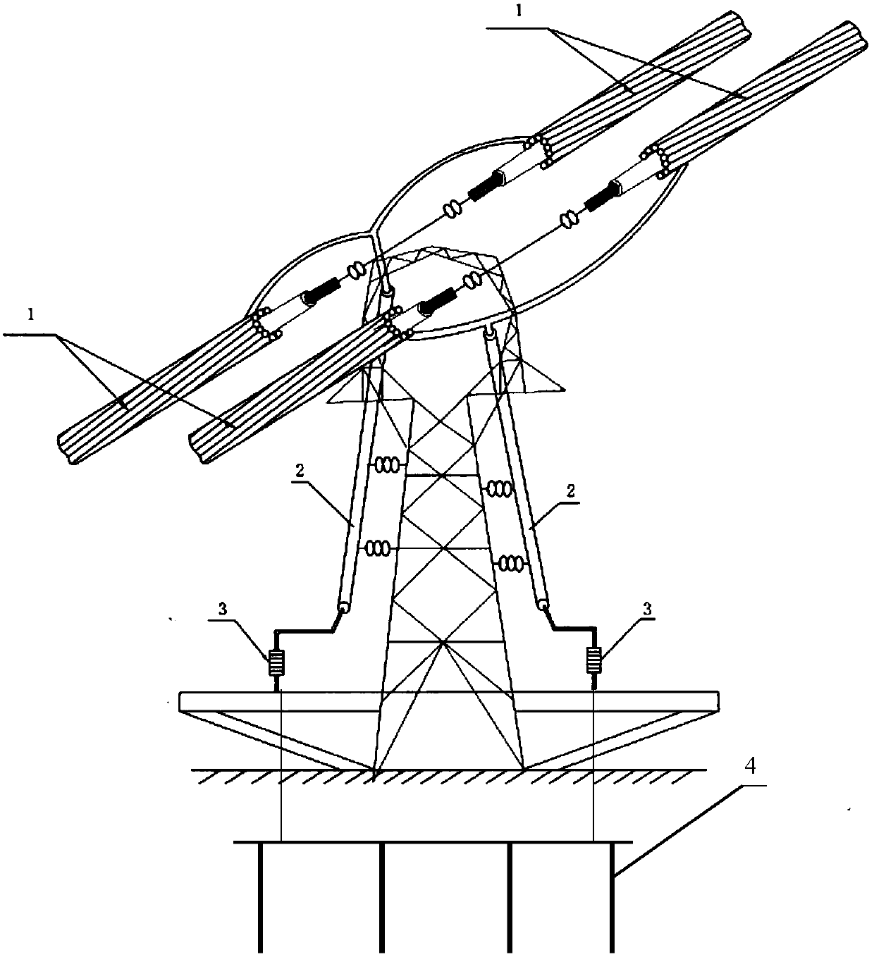
[0038] Such as figure 1 As shown, a method for suppressing the overvoltage at the head of a transmission line during lightning strikes includes the following steps:
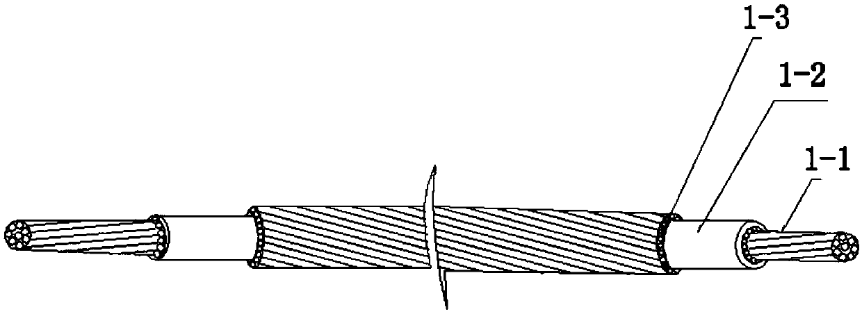
[0039] 1) Set the coaxial overhead cable 1 according to the wave impedance value of the overhead lightning protection line, and design the coaxial overhead cable 1 with a smaller wave impedance;
[0040] 2) Design low impedance coaxial cable down conductor 2;
[0041] 3) Connect and install the coaxial overhead cable 1, the coaxial cable down conductor 2 and the ground lightning arrester 3 on the iron tower in turn. The ground lightning arrester 3 is connected to the grounding grid 4, of which the coaxial overhead cable 1 is erected on the iron tower At the top, one end of the coaxial cable down conductor 2 is connected to the coaxial overhead cable line 1, the other end of the coaxial cable down conductor 2 is connected to the ground lightning arrester 3, and the coaxial cable down conductor 2 is set against the tower body , The ground lightning arrester 3 is arranged at the bottom of the iron tower, the grounding net 4 is arranged under the ground at the bottom of the iron tower, and the ground lightning arrester 3 is electrically connected to the grounding net 4;
[0042] 4) When lightning strikes the coaxial overhead cable 1, the lightning current sequentially passes through the coaxial overhead cable 1, the coaxial cable down conductor 2, the ground arrester 3 and the grounding grid 4, and finally flows into the ground. The connection will greatly reduce the tower head discharge and insulator discharge flashover failure, thereby reducing the trip rate of the line lightning strike and improving the reliability of the power supply.
[0043] Step 1) According to the calculation formula of wave impedance value To design overhead lightning protection lines with low wave impedance, where L is inductance and c is capacitance. From this formula, it can be known that when the capacitance increases, the wave impedance value is decreasing, so a coaxial overhead cable 1 with a lower wave impedance value can be designed.
[0044] A device designed according to the above method for suppressing the overvoltage at the tower head of a transmission line during lightning strikes, comprising a coaxial overhead cable 1, a coaxial cable down conductor 2, and a ground lightning arrester 3 installed at the bottom of the tower And the grounding network 4 set underground at the bottom of the tower, one end of the coaxial cable down conductor 2 is connected to the coaxial overhead cable line 1, and the other end of the coaxial cable down conductor is connected to the ground lightning arrester 3, the ground lightning arrester 3 It is electrically connected to the grounding grid 4, one end of the coaxial cable down conductor 2 is connected to the coaxial overhead cable line 1, the other end of the coaxial cable down conductor is connected to the ground lightning arrester 3, and the ground lightning arrester 3 is connected to the ground grid 4 Electrical connection, when lightning strikes the coaxial overhead cable 1, the lightning current passes through the coaxial overhead cable 1, the coaxial cable down conductor 2, the ground arrester 3 and the grounding grid 4, and finally flows into the ground.
[0045] Such as figure 2 As shown, the coaxial overhead cable 1 includes an inner core conductor 1-1, an insulating layer 1-2, and an outer conductor 1-3 arranged in order from the inside out. This design makes the coaxial overhead cable 1 suffer from When a lightning strikes, the lightning current can pass through quickly, and present a downward pilot effect on the outer layer of the overhead ground wire, that is, connect the equipotential value with the earth, and form an obvious potential difference with the phase conductor, prompting the lightning current to take the lead in the overhead The outer conductor 1-3 of the ground wire discharges, so as to prevent lightning from being struck by the live phase line; the inner core conductor 1-1 is made of steel wire, and the outer conductor 1-3 is made of aluminum foil. Low cost, and can play an effective conductive role.
[0046] Such as image 3 As shown, the coaxial cable down conductor 2 includes a polyvinyl chloride filling core 5, an inner conductor layer 6, a cross-linked polyvinyl chloride layer 7, an outer conductor layer 8 and a polyvinyl chloride shell 9 arranged in sequence from the inside out. The structural design has formed the low-wave impedance characteristics of the down conductor. When lightning strikes the line tower, the powerful lightning energy must be quickly transmitted to the underground grounding grid 4 to safely eliminate lightning. The coaxial cable down conductor 2 is designed like this It can withstand the high voltage and high current carried by lightning to ensure that no side flash discharge is generated to nearby objects.
[0047] Such as Figure 4 As shown, the ground arrester 3 is a zinc oxide arrester. When the lightning voltage intruding wave exceeds the breakdown strength of the protective gap, the gap is broken down, limiting the amplitude of the overvoltage that invades the electrical equipment. After the intruding wave passes, the gap insulation strength Self-recovery, so that electrical equipment can continue to run, zinc oxide arrester has a stronger ability to restore the insulation strength than ordinary gaps.

PUM

no PUM

Description & Claims & Application Information

We can also present the details of the Description, Claims and Application information to help users get a comprehensive understanding of the technical details of the patent, such as background art, summary of invention, brief description of drawings, description of embodiments, and other original content. On the other hand, users can also determine the specific scope of protection of the technology through the list of claims; as well as understand the changes in the life cycle of the technology with the presentation of the patent timeline. Login to view more.
Why Eureka
Try Eureka