Factory practical power factor compensation method

A power factor compensation and factory technology, applied in the field of electric power, can solve problems such as increased line power and power loss, increased equipment and line loss, and reduced equipment power utilization, so as to reduce power supply costs, improve power quality, and reduce calorific value Effect

Inactive Publication Date: 2019-04-05
GUANGZHOU PANYU POLYTECHNIC
View PDF3 Cites 2 Cited by
  • Summary
  • Abstract
  • Description
  • Claims
  • Application Information

AI Technical Summary

Problems solved by technology

The existence of reactive power in the power system will increase the capacity of equipment, increase the loss of equipment and lines, and increase the voltage drop of lines, resulting in a series of power quality problems such as voltage fluctuations and flicker, voltage sags, and equipment power utilization.
[0003] In the prior art, in the factory power supply system, there are a lot of equipment such as motors and transformers, most of which are inductive loads. They consume a large amount of reactive power while consuming active power. Because when the power factor is too low , which will increase the current in the transmission line, increase the power and energy loss on the line, and increase the loss of line voltage at the same time

Method used


Image

  • Factory practical power factor compensation method

Examples


Embodiment Construction

[0025] The following will clearly and completely describe the technical solutions in the embodiments of the present invention with reference to the accompanying drawings in the embodiments of the present invention. Obviously, the described embodiments are only some, not all, embodiments of the present invention. Based on the embodiments of the present invention, all other embodiments obtained by persons of ordinary skill in the art without creative efforts fall within the protection scope of the present invention.

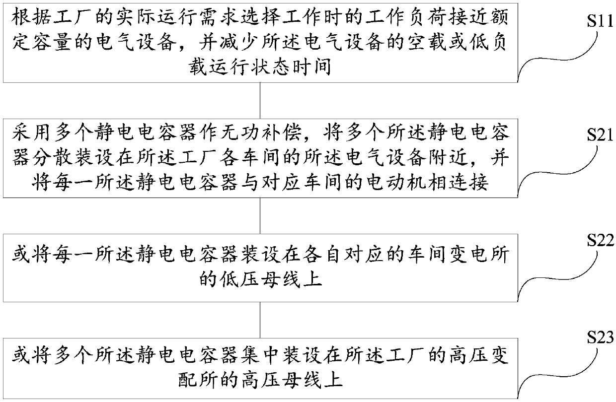
[0026] See figure 1 , the preferred embodiment of the present invention provides a factory practical power factor compensation method, at least including the following steps:

[0027] S11. Select electrical equipment whose working load is close to the rated capacity according to the actual operating requirements of the factory, and reduce the no-load or low-load operating state time of the electrical equipment;

[0028] In this embodiment, in the power supply syst...


PUM


Abstract

The invention discloses a factory practical power factor compensation method. The method comprises the steps of: selecting an electrical device with a work load when operation close to a rated capacity according to the actual operation demand of a factory, and reducing no-load or low-load operation state time of the electrical device; employing a plurality of electrostatic capacitors to perform reactive compensation to allow the electrostatic capacitors to be dispersedly arranged near the electrical device in each workshop of the factory and allow each electrostatic capacitor to be connected with a motor of a corresponding workshop; or arranging each electrostatic capacitor on a low-voltage but of a corresponding workshop substation; or integrally arranging the electrostatic capacitors tohigh-voltage buses of a high-voltage substation of the factory. The factory practical power factor compensation method can save the factory electric quantity and can reduce the loss of the electric energy of the factory.

Description

technical field [0001] The invention relates to the field of electric power technology, in particular to a factory practical power factor compensation method. Background technique [0002] Due to the application of a large number of inductive loads in the power system, there is an angle difference between the voltage and current in the phase, which leads to reactive power - the physical quantity that reflects the energy exchange between the power source and the load. The size of the reactive power indicates the difference between the power source and the load. The magnitude of energy exchange itself does not consume energy. At the same time, the flow of reactive power in the system has a great impact on the power system itself. The existence of reactive power in the power system will increase the capacity of equipment, increase the loss of equipment and lines, and increase the voltage drop of lines, resulting in a series of power quality problems such as voltage fluctuations...

Claims


Application Information

Patent Timeline
Patent Type & Authority Applications(China)
IPC IPC(8): H02J3/18
CPCH02J3/18Y02E40/30Y02P80/10
Inventor 罗宏霞
Owner GUANGZHOU PANYU POLYTECHNIC
Why Eureka
Try Eureka