Medical handcart with rapid moving device

A fast-moving, trolley technology, applied in the medical field, can solve the problems of limited trolley speed, affecting patient treatment, trolley damage, etc., to reduce mutual collisions, shorten moving time, and save physical strength.

Inactive Publication Date: 2019-04-09
嘉兴信益医疗器材有限公司
View PDF11 Cites 0 Cited by
  • Summary
  • Abstract
  • Description
  • Claims
  • Application Information

AI Technical Summary

Problems solved by technology

[0002] Medical trolley refers to the protective transfer medical equipment for wards. It is suitable for large hospitals, health clinics, pharmacies, mental hospitals and major daily use rotating trolleys. It can reduce the operating burden of caregivers to a large extent. The medical trolley There are many types of trolleys, and the types of trolleys used by different departments may be different. The medicines required by each ward are placed on the trolleys. On the way of medical staff pushing the trolleys, due to the large number of people and objects in the hospital corridors, the situation is complicated, and collisions will inevitably occur. The trolley causes damage or even injures others. According to a medical multifunctional trolley with the patent number CN 207912862 U, although it effectively protects the trolley from being damaged or injuring others, when it is necessary to transport medicines urgently, the medicines on the trolley Many, the trolley speed is limited, which may affect the treatment of patients

Method used


Image

  • Medical handcart with rapid moving device
  • Medical handcart with rapid moving device
  • Medical handcart with rapid moving device

Examples


Embodiment 1

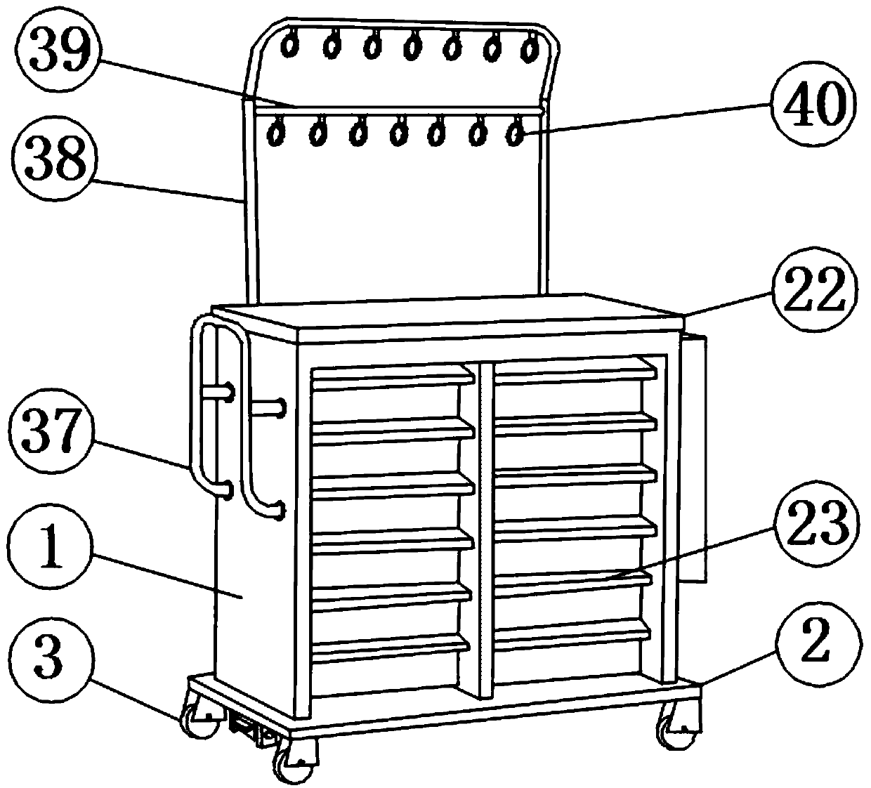
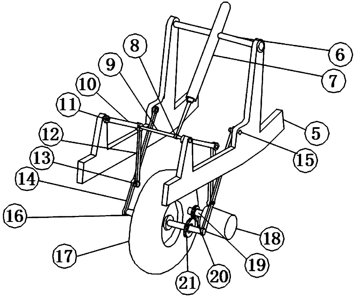
[0031] see Figure 1-6 According to an embodiment of the present invention, a medical trolley with a fast moving device includes a car body 1, the bottom of the car body 1 is fixedly connected to the bottom plate 2, and the four corners of the bottom plate 2 are fixedly connected to the universal wheels 3, so One side of the car body 1 is provided with a buffer device, and the side of the car body 1 close to the buffer mechanism has a cavity 4, and a fast moving device is arranged in the cavity 4, and the fast moving device includes a number There are two connecting frames 5, and the two connecting frames 5 are respectively fixedly connected to the side walls of the cavity 4, and the tops of the two connecting frames 5 are movably connected with the connecting rod one 6, and the hydraulic pressure The telescopic rod 7 is embedded in the middle part of the connecting rod one 6, the other end of the hydraulic telescopic rod 7 is fixedly connected with the ring 8, and the ring 8 ...

Embodiment 2

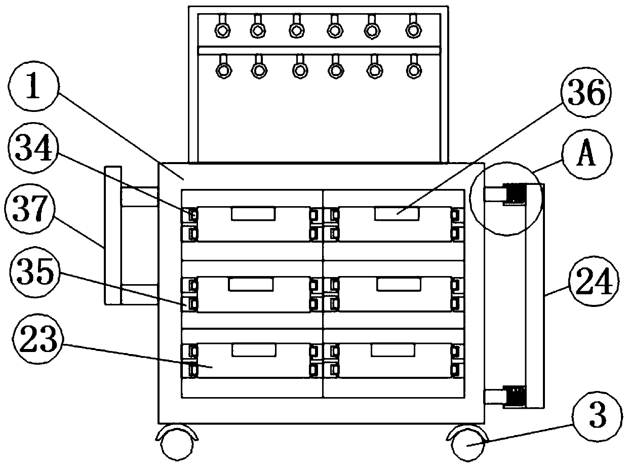
[0034] see Figure 1-5, for the buffer device, the buffer device includes a rubber plate 24, a support rod 1 25, a sleeve 26 and a limit block 27, and the side of the vehicle body 1 close to the fast moving device is provided with a rubber plate 24, The rubber plate 24 is fixedly connected to the sleeve 26 at the top and the bottom of the side close to the car body 1, and the outer wall of the car body 1 is fixedly connected to the support rod one 25 near the sleeve 26, and the support rod one 25 One end away from the vehicle body 1 is located inside the sleeve 26 and is fixedly connected with the stop block 27; for the sleeve 26, a return spring 28 is provided inside the sleeve 26, and the return spring 28 One end of the spring is fixedly connected with the sleeve 26, and the other end of the return spring 28 is fixedly connected with the stop block 27; for the sliding device, the sliding device includes a sliding block 34 and a slide groove 35, the The both sides of storage...

Embodiment 3

[0037] see Figure 6 , for the fixing device, the fixing device includes a support rod 29, a support plate 30, a damping shaft 31 and a fixed block 32, the bottom of the bottom plate 2 is fixedly connected with two support rods 29, and the two A support plate 30 is provided between the two support bars 29, the support plate 30 is movably connected with the two support bars 29 through a damping rotating shaft 31, and two fixed blocks 32 are fixedly connected under the support plate 30; As for the support plate 30 , the side of the support plate 30 away from the buffer device is fixedly connected to the pedal 33 .

[0038] Through the above scheme of the present invention, when the trolley does not need to move, the fixing device can be put down through the foot pedal 33 to fix the trolley, so as to avoid being pushed away by others due to the large flow of people.

[0039] To sum up, with the help of the above technical solution of the present invention, some medicines can be ...


PUM


Abstract

The invention discloses a medical handcart with a rapid moving device. The medical handcart comprises a handcart body, wherein the bottom of the handcart body is fixedly connected with a bottom plate;a buffer device is arranged on one side of the handcart body; a cavity is opened in one side of the handcart body close to a buffer mechanism; the rapid moving device is arranged in the cavity; the rapid moving device comprises two connecting racks; the two connecting racks are fixedly connected with a side wall of the cavity, respectively; a fixing device is arranged on one side of the bottom plate remote from the rapid moving device; the top of the handcart body is fixedly connected with a storage platform; a plurality of storage boxes are arranged inside the handcart body; the storage boxes are movably connected with the handcart body by a sliding device; and a hanging device is arranged above the storage platform. The invention has the beneficial effects that the medical handcart is provided with the rapid moving device, so that a moving speed of the handcart can be increased by the rapid moving device when medicines are urgently transported, thereby saving physical strength of medical staffs and shortening moving time required for the handcart.

Description

technical field [0001] The invention relates to the field of medical technology, in particular to a medical trolley with a fast moving device. Background technique [0002] The medical trolley refers to the protective transfer medical equipment for the ward. It is suitable for large hospitals, health clinics, pharmacies, mental hospitals and major daily use rotating trolleys. It can greatly reduce the operating burden of the nurses. The medical trolley There are many types of trolleys, and the types of trolleys used by different departments may be different. The medicines required by each ward are placed on the trolleys. On the way of medical staff pushing the trolleys, due to the large number of people and objects in the hospital corridors, the situation is complicated, and collisions will inevitably occur. The trolley causes damage or even injures others. According to a medical multifunctional trolley with the patent number CN 207912862 U, although it effectively protects ...

Claims


Application Information

Patent Timeline
Patent Type & Authority Applications(China)
IPC IPC(8): A61G12/00
CPCA61G12/001
Inventor 张益军
Owner 嘉兴信益医疗器材有限公司
Why Eureka
Try Eureka